Yaskawa GPD503 Drive User Manual
Page 42
2.8 DC INJECTION BRAKING Continued
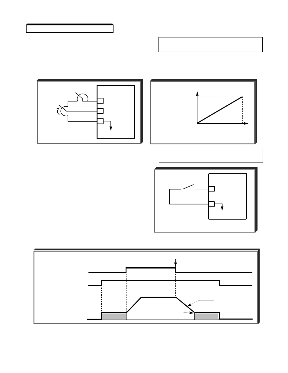
C. Sn-19: Multi-function Analog
Data
07
: DC Injection Braking
Input (Term. 16)
Current Adjust
The multi-function analog input at terminal 16 may be configured to allow analog control
of the amount of DC injection braking current (from 0% to 100% of the current level set in
Cn-11), which directly controls the amount of DC injection voltage applied to the motor.
D. Sn-15 thru Sn-18: Multi-function
Data
60
: DC Injection Braking
Inputs (Term. 5 thru 8)
Command
Any multi-function input terminal can be
utilized to control DC injection braking. When
used, DC injection current will be applied until
the input is removed, provided that the GPD
503 output frequency is below the DC Braking
Start Frequency (Cn-10).
EXAMPLE:
Sn-18 =
60
Contact input at Terminal 8 is
the DC Injection Braking Command
DC Braking Sequence
o
o
o
GPD 503
8 DC INJ. BRK.
COMMAND
11
0V
RUN COMMAND
DC INJECTION
BRAKING COMMAND
OUTPUT FREQUENCY
STOP
RAMP TO STOP
DC
DC
DC INJ. BRK. START
FREQUENCY (Cn-10)
BRAKING
CURRENT
ADJUST
1R
GPD 503
15 +15V
16 0-10V (20K
1
)
17
C
100
BRAKING
CURRENT
(%)
(Cn-11)
0
10
ANALOG VOLTAGE
2-11