12 external fault inputs – Yaskawa GPD503 Drive User Manual
Page 46
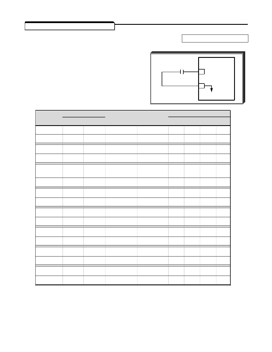
2.12 EXTERNAL FAULT INPUTS
A. Sn-12: External Fault Signal Input
Factory setting:
0100
(Terminal 3)
This constant determines how the GPD 503
responds to an external fault contact input on
terminal 3. The chart below lists the possible
settings, and indicates how the GPD 503 will
interpret the input signal.
Sn-12
Term. 3 (Note 1)
Always
During
Mode (Note 2)
Data
N.O. N.C.
Detected
Operation
0
1
2
3
0000
X
X
X
0001
X
X
X
0010
X
X
X
0011
X
X
X
0100
X
X
X
(Factory Set)
0101
X
X
X
0110
X
X
X
0111
X
X
X
1000
X
X
X
1001
X
X
X
1010
X
X
X
1011
X
X
X
1100
X
X
X
1101
X
X
X
1110
X
X
X
1111
X
X
X
NOTES
1.
N.O. = normally open contact; N.C. = normally closed contact.
2.
Mode 0 = Ramp to Stop (bn-02); Mode 1 = Coast to Stop;
Mode 2 = Emergency Stop (bn-04);
Mode 3 = Continue operation (minor fault).
EXTERNAL
FAULT
CONTACT
GPD 503
3
11
0V
Sn-12 Term. 3 (Note 1) Always
During
Mode (Note 2)
Data
N.O. N.C.
Detected
Operation
0
1
2
3
2-15