A7-6 – Yaskawa GPD503 Drive User Manual
Page 155
Advertising
6. The Braking Unit and Braking Resistor Unit MUST BE GROUNDED. Observe the
following precautions:
• Use grounding leads conforming to your National Electrical Code.
• If the installation requires the Braking Resistor Unit to be used without its
enclosure (with grounding terminal), ground it by attaching a ground lead
at one of the mounting screws.
• Grounding resistance of the Braking Unit should be 100 ohms or less.
A7-6
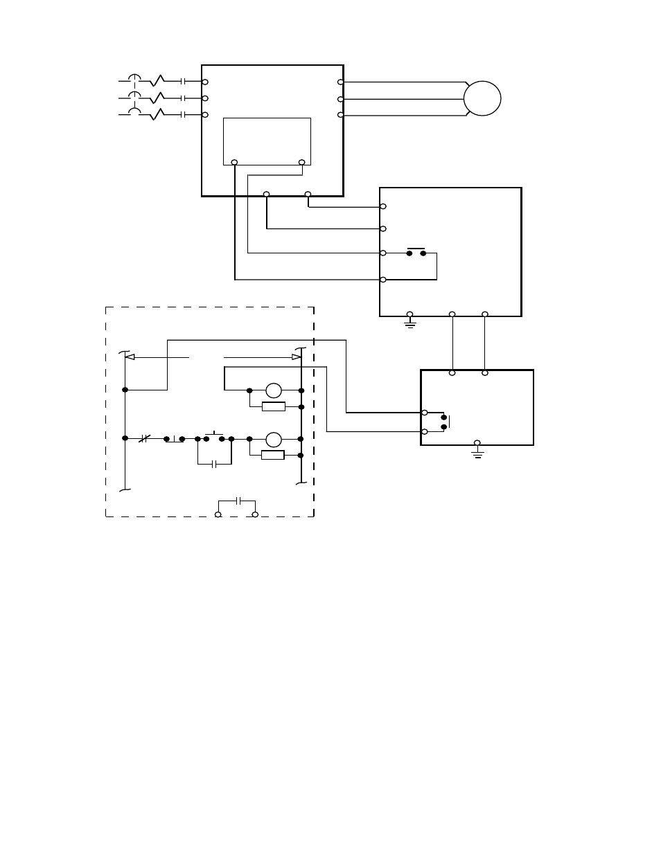
Figure A7-4. Wiring Single Braking Unit and Braking Resistor Unit to Drive
(230V 15-30HP(CT), 460V 25-60HP(CT), 575V 30-50HP(CT))
T1
T2
T3
R
S
T
U
V
W
GPD 503
CONTROL
PCB
3
11
B0/–
B1/+
PART OF USER SUPPLIED
EXTERNAL
CIRCUIT
BRAKING
UNIT
B
P
N
3
1OL
1M
1M
1M
CB
L1
L2
L3
120VAC
THRX
FAULT
CONTACT
THRX
RC
1M
RC
1M
THRX
POWER
ON
POWER
OFF
BRAKING
RESISTOR
UNIT
1
2
1THG
B
P
P
o
GND
(E)
4
Advertising
See also other documents in the category Yaskawa Equipment:
- Tag Generator (30 pages)
- MP3300iec (82 pages)
- 1000 Hz High Frequency (18 pages)
- 1000 Series (7 pages)
- PS-A10LB (39 pages)
- iQpump Micro User Manual (300 pages)
- 1000 Series Drive Option - Digital Input (30 pages)
- 1000 Series Drive Option - CANopen (39 pages)
- 1000 Series Drive Option - Analog Monitor (27 pages)
- 1000 Series Drive Option - CANopen Technical Manual (37 pages)
- 1000 Series Drive Option - CC-Link (38 pages)
- 1000 Series Drive Option - CC-Link Technical Manual (36 pages)
- 1000 Series Drive Option - DeviceNet (37 pages)
- 1000 Series Drive Option - DeviceNet Technical Manual (81 pages)
- 1000 Series Drive Option - MECHATROLINK-II (32 pages)
- 1000 Series Drive Option - Digital Output (31 pages)
- 1000 Series Drive Option - MECHATROLINK-II Technical Manual (41 pages)
- 1000 Series Drive Option - Profibus-DP (35 pages)
- AC Drive 1000-Series Option PG-RT3 Motor (36 pages)
- Z1000U HVAC MATRIX Drive Quick Start (378 pages)
- 1000 Series Operator Mounting Kit NEMA Type 4X (20 pages)
- 1000 Series Drive Option - Profibus-DP Technical Manual (44 pages)
- CopyUnitManager (38 pages)
- 1000 Series Option - JVOP-182 Remote LED (58 pages)
- 1000 Series Option - PG-X3 Line Driver (31 pages)
- SI-EN3 Technical Manual (68 pages)
- JVOP-181 USB Copy Unit (2 pages)
- JVOP-181 (22 pages)
- SI-EN3 (54 pages)
- MECHATROLINK-III (35 pages)
- SI-ET3 (49 pages)
- EtherNet/IP (50 pages)
- SI-EM3 (51 pages)
- 1000-Series Option PG-E3 Motor Encoder Feedback (33 pages)
- 1000-Series Option SI-EP3 PROFINET (56 pages)
- PROFINET (62 pages)
- AC Drive 1000-Series Option PG-RT3 Motor (45 pages)
- SI-EP3 PROFINET Technical Manual (53 pages)
- A1000 Drive Option - BACnet MS/TP (48 pages)
- 120 Series I/O Modules (308 pages)
- A1000 12-Pulse (92 pages)
- A1000 Drive Software Technical Manual (16 pages)
- A1000 Quick Start (2 pages)
- JUNMA Series AC SERVOMOTOR (1 page)
- A1000 Option DI-101 120 Vac Digital Input Option (24 pages)