Section 3. digital operator, 1 general, 2 display and keypad – Yaskawa GPD503 Drive User Manual
Page 93
Section 3. DIGITAL OPERATOR
3.1 GENERAL
The Digital Operator enables the GPD 503 to be
operated in either the Drive (DRIVE) mode or the
Program (PRGM) mode. The Program mode enables
the operator to enter information into the
GPD 503's memory to configure the GPD 503 to the
application. In the Drive mode, the GPD 503
controls motor operation. Switching between the
two modes can only be done when the GPD 503 is
in a stopped condition.
3.2 DISPLAY AND KEYPAD
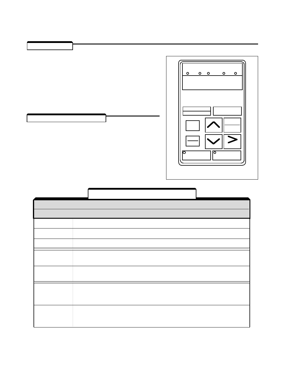
The Digital Operator has a 5 digit LED display.
Both numeric and alphanumeric data can appear
on the display, but because 7-segment LEDs are
used, the number of alphabetic characters is
limited.
Indicator lamps and keys on the Digital Operator
are described in Table 3-1.
A. INDICATOR LAMPS
NAME
FUNCTION
DRIVE
Lights when the GPD 503 is in the Drive mode of operation.
FWD
Lights when Forward motor run has been selected.
REV
Lights when Reverse motor run has been selected.
REMOTE
Lights when the GPD 503 is programmed to operate from external RUN
SEQ
and STOP signals.
REMOTE
Lights when the GPD 503 is programmed to operate by an external
REF
frequency reference signal.
RUN
Off when GPD 503 is in stopped condition; lights steadily when Run signal
is active; blinks after Stop signal has been received and GPD 503 output
is ramping down. (See Figure 3-2.)
STOP
Lights steadily at initial power-up; blinks after Run signal becomes active
but frequency reference is zero; off when GPD 503 output is controlling
motor speed. (See Figure 3-2.)
Figure 3-1. Digital Operator
Table 3-1. Digital Operator Controls
A. INDICATOR LAMPS
NAME
FUNCTION
3-1
DIGITAL
OPERATOR
PRGM
DRIVE
DATA
ENTER
REMOTE
DRIVE FWD REV SEQ REF
DSPL
JOG
RESET
FWD
REV
RUN
STOP