System interface signals, System interface signals -44 – Altera JESD204B IP User Manual
Page 125
System Interface Signals
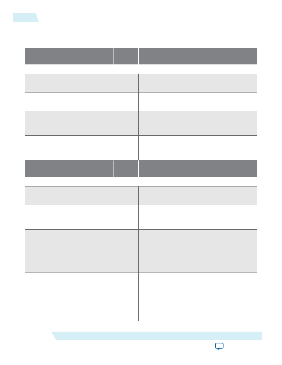
Table 5-21: Interface Signals
Signal
Clock
Domain
Direction
Description
Clocks and Resets
device_clk
—
Input
Device clock signal from the external converter or
clock device.
mgmt_clk
—
Input
Management clock signal from the on-board 100
MHz oscillator.
frame_clk
—
Output
Internally generated clock. The Avalon-ST user data
input must be synchronized to this clock domain for
normal operation mode.
global_rst_n
mgmt_clk
Input
Global reset signal from the push button. This reset is
an active low signal and the deassertion of this signal
is synchronous to the rising-edge of
mgmt_clk
.
Signal
Clock
Domain
Direction
Description
JESD204B
tx_sysref[LINK-1:0]
link_clk
Input
TX SYSREF signal for JESD204B Subclass 1
implementation.
sync_n[LINK-1:0]
link_clk
Input
Indicates a TX
SYNC_N
from the receiver. This is an
active low signal and is asserted 0 to indicate a
synchronization request or error reporting.
mdev_sync_n[LINK-1:0]
link_clk
Input
Indicates a multidevice synchronization request at
the TX path. Synchronize signal combination should
be done externally and then input to the JESD204B
IP core through this signal. In a single link instance
where multidevice synchronization is not needed,
you need to tie this signal to the
dev_sync_n
signal.
alldev_lane_aligned
link_clk
Input
Aligns all lanes for this device at the RX path.
For multidevice synchronization, multiplex all the
dev_lane_aligned
signals before connecting to this
signal pin.
For single device support, connect the
dev_lane_
aligned
signal back to this signal.
5-44
System Interface Signals
UG-01142
2015.05.04
Altera Corporation
JESD204B IP Core Design Guidelines