Altera JESD204B IP User Manual
Page 83
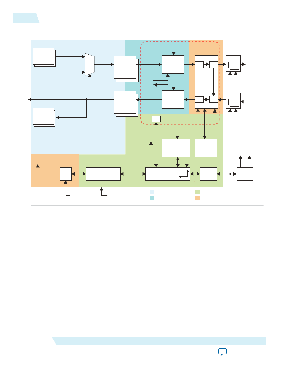
Figure 5-1: Design Example Block Diagram
Pattern
Generator
Sample
Mapper
(2)
(3)
(3)
(2)
(3)
(6)
PCS
Ser
PCS
Des
Deassembler
(Transport
Layer)
Avalon-ST
32 Bit
RX Base
Core
(Link Layer)
Duplex
SerDes
PHY
32 Bit
32 Bit
sync_n
rx_dev_sync_n
DAC
sync_n
ADC
rx_dev_sync_n
SPI
Device
Clock
tx_sysref
Device
Clock
rx_sysref
SPI
Avalon-ST User Data
Avalon-ST User Data
test_mode
Pattern
Generator
(2)
Pattern
Checker
(2)
(3)
(3)
0
(4)
(4)
(5)
(8)
(5)
(4)
(4)
Transceiver
Reconfiguration
Controller
Transceiver
Reset
Controller
Reconfig
Ready
Reset
Status rx_seriallpbken
Control Unit (CU)
(10)
Avalon-MM
ROM
SPI
Master (7)
Avalon-MM
Clock and
SYSREF
Device
Clock
tx_sysref
rx_sysref
PLL Reconfiguration
(11)
Avalon-MM
Frame Reset
Link Reset
Avalon-MM Slave Reset
CSR
PLL
(9)
reconfig
1: Frame Clock
2: Link Clock
Device Clock
Management Clock
JESD204B IP Core
(Duplex)
(1)
(11)
1: Frame Clock Domain
2: Link Clock Domain
Management Clock Domain (100 MHz)
Device Clock Domain
Assembler
(Transport
Layer)
Avalon-ST
Avalon-ST
32 Bit
TX Base
Core
(Link Layer)
tx_sysref
rx_sysref
The list below describes the mechanism of the design example architecture (with reference to the note
numbers in the design example block diagram).
1. For multiple links, the JESD204B IP core is instantiated multiple times. For example, in 2x112 (LMF)
configuration, two cores are instantiated, where each core is configured at LMF=112.
(27)
2. The number of pattern generator or pattern checker instances is equivalent to the parameter value of
LINK. The data bus width per instance is equivalent to the value of FRAMECLK_DIV*M*S*N.
(27)
3. The number of transport layer instances is equivalent to the parameter value of LINK. The legal value
of LINK is 1 and 2. The data bus width per instance is equivalent to the value of
FRAMECLK_DIV*M*S*N.
(27)
The
test_mode
= 0 signal indicates a normal operation mode, where the
assembler takes data from the Avalon-ST source. Otherwise, the assembler takes data from the pattern
generator.
4. The Avalon-ST interface data bus is fixed at 32-bit. The number of 32-bit data bus is equal to the
number of lanes (L).
5. The number of lanes per converter device (L).
(27)
Refer to
and
for the illustration of a single and multiple JESD204B links.
5-2
JESD204B IP Core Design Example
UG-01142
2015.05.04
Altera Corporation
JESD204B IP Core Design Guidelines