Altera JESD204B IP User Manual
Page 43
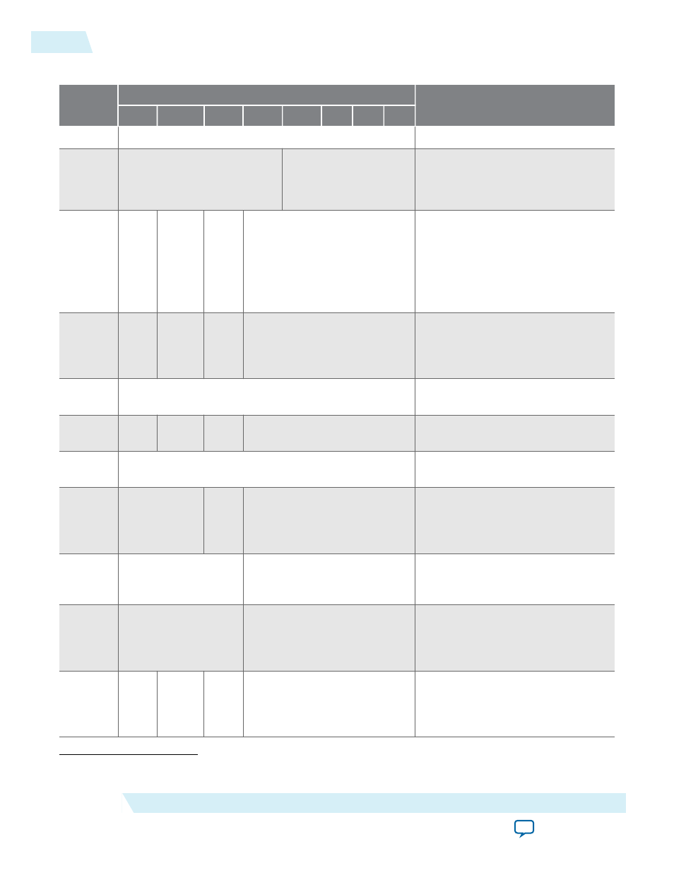
Table 4-1: Link Configuration Data Transmitted in ILAS Phase
Configura‐
tion Octet
Bits
Description
MSB
6
5
4
3
2
1
LSB
0
DID[7:0]
DID = Device ID
1
ADJCNT[3:0]
BID[3:0]
ADJCNT = Number of adjustment
resolution steps
(16)
BID = Bank ID
2
0
ADJDI
R
PHA
DJ
LID[4:0]
ADJDIR = Direction to adjust DAC
LMFC
(16)
PHADJ = Phase adjustment
request
(16)
LID = Lane ID
3
SCR
0
0
L[4:0]
SCR = Scrambling enabled/disabled
L = Number of lanes per device
(link)
4
F[7:0]
F = Number of octets per frame per
lane
5
0
0
0
K[4:0]
K = Number of frames per multi-
frame
6
M[7:0]
M = Number of converters per
device
7
CS[1:0]
0
N[4:0]
CS = Number of control bits per
sample
N = Converter resolution
8
SUBCLASSV[2:0]
N_PRIME[4:0]
SUBCLASSV = Subclass version
N_PRIME = Total bits per sample
9
JESDV[2:0]
S[4:0]
JESDV = JESD204 version
S = Number of samples per
converter per frame
10
HD
0
0
CF[4:0]
HD = High Density data format
CF = Number of control words per
frame clock per link
(16)
Applies to Subclass 2 only.
4-6
TX ILAS
UG-01142
2015.05.04
Altera Corporation
JESD204B IP Core Functional Description