Figure 6-3 – Altera JESD204B IP User Manual
Page 142
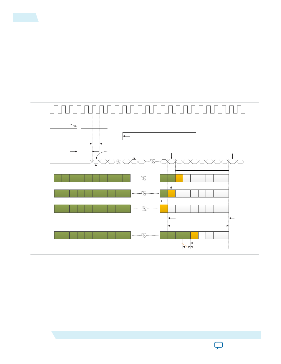
Figure 6-3: Early RBD Release Opportunity for Latest Arrival Lane Across Two Local Multi-Frames
Scenario
In this example, the RBD count varies from 7 to 1; the /R/ character is received at the previous local multi-
frame when the RBD count = 1; the /R/ character is received at the current local multi-frame when the
RBD count = 0 and 7. In this scenario, deterministic latency is not guaranteed because the RBD elastic
buffer is released either at the current LMFC boundary when the RBD count = 0 and 1, or one local multi-
frame period later at the next LMFC boundary when the RBD count = 7. You can fix this issue by setting
the RBD offset so that the RBD elastic buffer is always released at the next local multi-frame. Setting
csr_rbd_offset = 5 forces the release of RBD elastic buffer 5 LMFC counts before the next LMFC boundary.
This corresponds to LMFC count of 3 at the current local multi-frame. In this scenario, setting
csr_rbd_offset not only optimizes user data latency through the IP core, it also resolves the deterministic
latency issue.
1st LMFC
boundary
SYSREF pulse is
sampled by IP core ‘s
internal register
2 link clock cycle deterministic
delay from SYSREF sampled
high to LMFC zero-crossing
Link clock
Free running LMFC counter
Internal
LMFC Counter
0
K
SYNC_N deasserted directly
after LMFC boundary
K
K
K
K
R
K
K
K
K
K
Latest arrival
lane in first
power cycle
D
D
D
D
K
K
RBD count = 7
K
K
K
K
K
K
K
K
K
K
K
Latest arrival
lane in second
power cycle
R
D
D
D
RBD count = 0
K
K
K
K
K
D
K
K
K
K
K
Latest arrival
lane in fifth
power cycle
D
D
D
D
R
Next LMFC
boundary
RBD count = 1 with reference to the current LMFC boundary
K
K
K
K
K
K
K
K
K
K
K
Aligned
outputs on all
lanes
K
R
D
D
K
K
1 link clock or LMFC
count to cater for
power cycle variation
RBD Elastic
Buffers Released
Set csr_rbd_offset = 5
1 link clock period = LMFC count
7 LMFC counts with
reference to the next
LMFC boundary
Internal LMFC counter resets
Current LMFC
boundary
D
D
RBD elastic buffer is released at the current
LMFC boundary during the second and
fifth power cycle when csr_rbd_offset = 0
RBD elastic buffer
is released at the
next LMFC
boundary during
the first power
cycle when
csr_rbd_offset = 0
Latency variation = 1 local multi-frame period
D
D
D
D
D
D
D
D
D
rx_sysref
SYNC_N
2nd LMFC
boundary
1
2
0
0
1
2
3
4
5
6
7
0
1
7
1
2
In the example above, lane de-skew error could happen if the sum of the difference of /R/ character’s
LMFC count in the earliest arrival lane to the latest arrival lane, and the number of LMFC count up to the
release of RBD elastic buffer exceeds the RBD elastic buffer size. If this is the root cause of lane de-skew
error, setting RBD offset is one of the techniques to overcome this issue. Not every RBD offset value is
legal. Figure below illustrates the technique to decide the legal RBD offset value.
6-4
Programmable RBD Offset
UG-01142
2015.05.04
Altera Corporation
JESD204B IP Core Deterministic Latency Implementation Guidelines