Signals, Signals -26 – Altera JESD204B IP User Manual
Page 63
The bring-up sequence:
1. Ensure that the core PLL and transceiver PLL are out of reset first.
If the Transceiver PHY Reset Controller and Transceiver Reconfiguration blocks rely on the clock
from the core PLL output (for example, the management clocks and reset), then the core PLL must be
out of reset first. If the Transceiver PHY Reset Controller and Transceiver Reconfiguration blocks are
clocked by the external clock generator, the core PLL and transceiver PLL can be out of reset
concurrently.
2. Deassert the transceiver reset.
3. Ensure that all core PLL and transceiver PLL are locked.
4. Once the transceiver is out of reset, deassert the AV-MM interface reset for the IP core. At the configu‐
ration phase, the subsystem can program the converter devices through the SPI interface. During this
configuration phase, the subsystem may program the JESD204B IP core if the default IP core register
settings need to change.
5. Deassert both the link reset for the IP core and the frame reset for the transport layer.
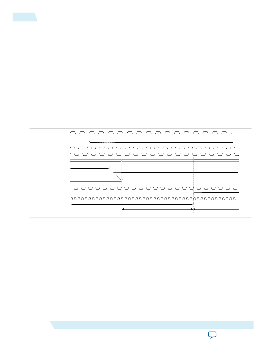
Figure 4-9: Reset Sequence Timing Diagram
pll_ref_clk (tx/rx pll)
GENERIC STATES
TRANSCEIVER & PLL POWERUP
JESD204B IP OPERATION
pll_locked (from TX PLL)
txlink_clk/rxlink_clk
txlink_rst_n/rxlink_rst_n
txframe_clk/rxframe_clk
txframe_rst_n/rxframe_rst_n
JESD204B IP core register configuration and converter devices SPI programming
JESD204B IP core link initialization begins
AVALON SLAVE CONFIGURATION PHASE
reconfig_clk (Arria 10 only)
Transceiver PHY Reset Controller
reset input (active high)
jesd204_tx_avs_clk/
jesd204_rx_avs_clk
Transceiver PHY Reset Controller
tx_ready/rx_ready
jesd204_tx_avs_rst_n/
jesd204_rx_avs_rst_n
Signals
The JESD204B IP core signals are listed by interface:
• Transmitter
• Receiver
Note: You should terminate any unused signals.
4-26
Signals
UG-01142
2015.05.04
Altera Corporation
JESD204B IP Core Functional Description