Logic names, Output operations, Virtual outputs – Basler Electric BE1-BPR User Manual
Page 111: Logic names -5, Output operations -5, Virtual outputs -5
9272000990 Rev J
BE1-BPR BESTlogic Programmable Logic
5-5
LOGIC NAMES
In order to easily identify the logic scheme that is operational in memory, each logic scheme is named.
The name is shown on the RELAY SETUP menu screen. For the custom logic scheme, the operator must
enter a name (a maximum of eight characters) identifying the logic scheme. When naming a custom logic
scheme, the standard logic scheme names cannot be used. Only a unique name can be assigned to a
custom logic scheme. Custom logic schemes are programmed through the communication ports.
Preprogrammed logic schemes are selected through the front panel or the communication ports. A logic
scheme is selected by using the command LOGIC = <name> where <name> is the defined name of the
logic scheme.
If a custom logic scheme is to be used, it is defined starting with the command LN = <name> where
<name> is the user-selected name for the logic scheme.
To simplify making minor changes to an existing logic scheme, all logic equations for an existing scheme
can be copied over to the custom scheme by typing LN=<existing name>. Then the custom logic scheme
must be given a unique name by entering LN=<custom name>. Once the logic name is changed, the
changes can be made. (Changing the name does not affect the other logic definitions.) If changes are
attempted prior to changing the logic name, the relay will respond with an error message:
CUSTOM
LOGIC NAME NOT SELECTED.
LN
Custom logic scheme
HMI Menu Branch: 1
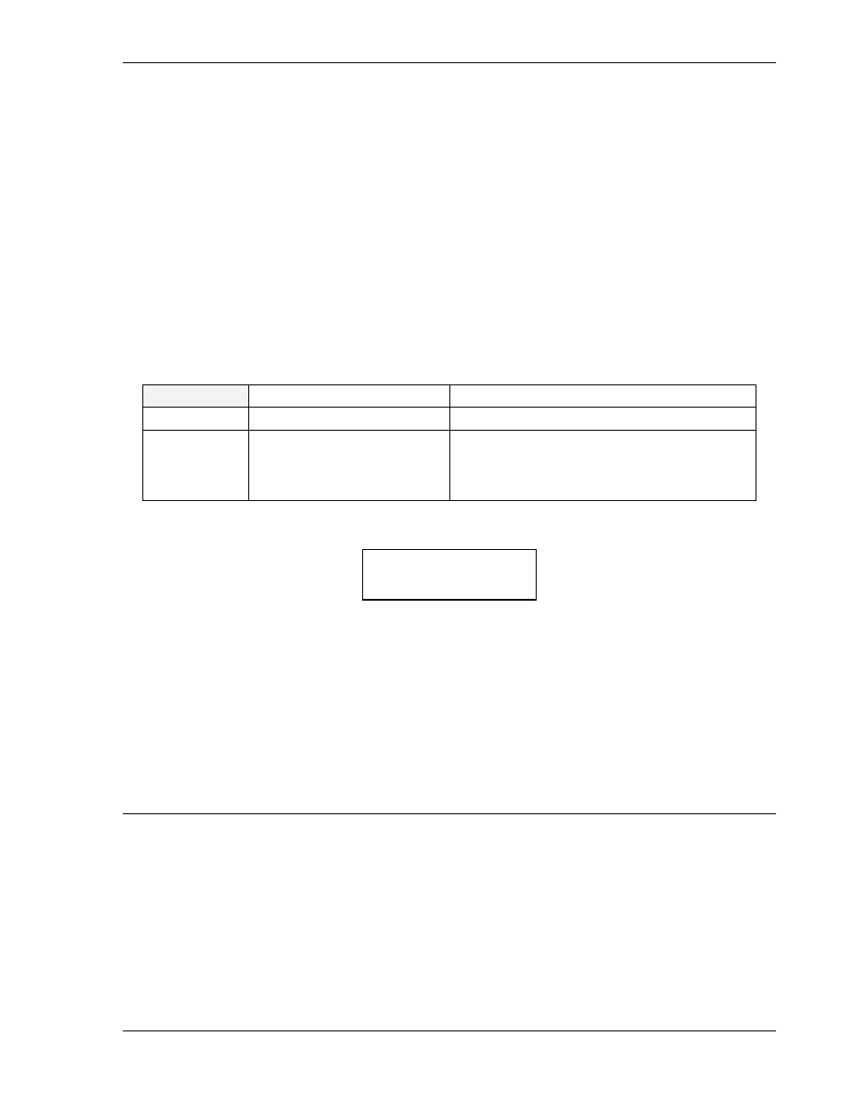
Parameter
Range
Comments
existing name
1 to 8 characters
Defined name must be different from the
standard logic names. An existing logic
scheme can be copied into memory for editing
by using LN=<existing command>.
LN HMI Screen Example:
LN Command
Purpose:
Read the name of the active logic or program a new set of logic equations called
<name>.
Syntax:
LN[=<name>]
Comments:
An access area one password is required to change settings.
LN Command Example:
Read the name of the active logic.
LN
BFL1
OUTPUT OPERATIONS
The BE1-BPR relay provides two types of outputs: virtual outputs and hardware outputs. The following
paragraphs provide information about the function and characteristics of virtual and hardware outputs.
Virtual Outputs
A virtual output exists only as a logical state inside the relay. Output operation for virtual outputs OA
through O12 is defined by Boolean logic equations. Each variable in the equation corresponds to the
current state of an input, output, or timer. Any time a logic variable changes state, the outputs are
reevaluated as TRUE or FALSE. If a logical output corresponding to a physical output changes state,
then the corresponding output relay contact also changes state.
Logic equations are defined by the logic variables, logical operators, and their position in the equation.
The logical operators are AND (*), OR (+), and NOT (/). Logical operator AND (*) is assumed between
RELAY SETUP
LOGIC = BFL1