Figure 4-6. timer circuit – Basler Electric BE1-BPR User Manual
Page 72
4-20
BE1-BPR Functional Description
9272000990 Rev J
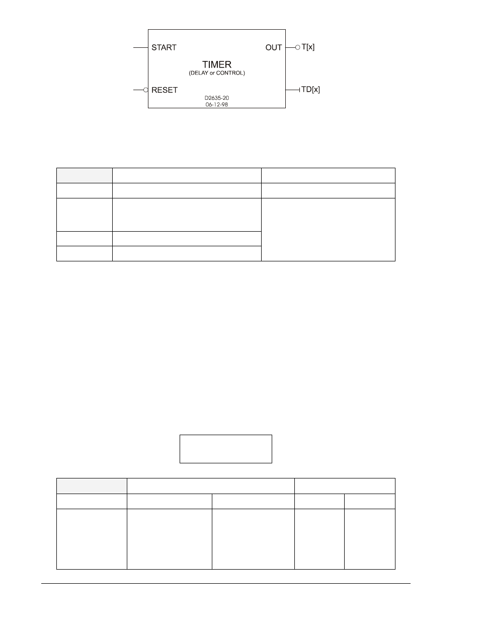
Figure 4-6. Timer Circuit
The LT command is used to configure timers for control or delay operation and define the start and reset
logic.
LT
Timer logic
HMI Menu Branch: N/A
Parameter
Parameter Selections
Defaults
type
C (control timer)
D (delay timer)
0 (disabled)
LT1=D,O8,/O8
LT2=D,O9,/O9
LT3=0,0,0
LT4=D,O6,/O6
LT5=D,O12,/O12
LT6=0,0,0
start
any logic variable
reset
any logic variable
LT Command
Purpose:
Read or change timer logic.
Syntax:
LT[x][=<type>,<start>,<reset>]
Comments:
x = the number of the timer being read or changed (1, 2, 3, 4, 5, or 6). An access area 1
password is required to change settings.
LT Command Example:
Configure timer 1 as a delay timer that is started when contact input 1 is energized and stopped when
output 6 is de-energized. Configure timer 2 as a control timer that is started when input 2 is energized and
stopped when input 2 is de-energized.
LT1=D,I1,/O6; LT2=C,I2,/I2
The TD command is used to read or enter the delay settings for each of the six timers.
TD HMI Screen Example:
TD
Timer delays ∗
HMI Menu Branch: 1
Parameter
Unit of Measure
Range
Increment
Default
delay
cycles (c)
milliseconds (m)
seconds (s)
1 to 3,600 cycles
10 to 60,000 ms
1 to 60 seconds
1 cycle
1 ms
0.1 s
TD1=150m
TD2=200m
TD3=1.0s
TD4=500m
TD5=30.0s
TD6=0m
∗
All timer settings greater than or equal to 1 second are rounded to 0.1 second resolution.
TD1 TD2 TD3
150m 200m 1.0s