Breaker failure logic 2 for standard relays (bfl2) – Basler Electric BE1-BPR User Manual
Page 37
9272000990 Rev J
BE1-BPR Application
2-13
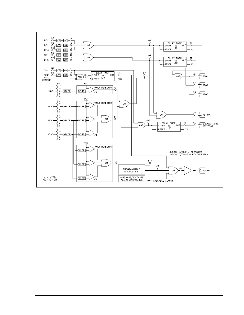
5. Retrip Output. A Retrip output is provided to give a backup trip signal to the breaker trip coil. This can
either provide a separate path to a single trip coil or be hooked to the backup trip coil if available.
6. Alarm Output. An Alarm output is provided to signal relay failure or diagnostic alarm.
Figure 2-16. BFL1 Logic
Breaker Failure Logic 2 for Standard Relays (BFL2)
BFL2 logic (shown in Figure 2-17) provides the following application features.
1. Three-Pole Tripping BF Logic (Features: Output latch-in provided and Control timer limits operational
window). Three BFI inputs are available at IN3, IN4, and IN5 to start delay timer T1. If the BFI inputs
are not reset by the time timer 1 times out and either the phase (F1) or neutral (F2) fault detector is
picked up, BFO1-3 will close (OUT1-3), tripping the backup breakers. A control timer (T3) is used to
limit the breaker failure window of opportunity. Refer to the breaker failure timing diagram in Section 1
for information on setting the delay and control timers.
2. Single-Pole Tripping BF Logic (Features: Output latch-in provided and Control timer limits operational
window). If single-pole tripping is used, two additional BFI inputs are available (IN6 and IN7) to start
delay timer T2. These inputs are only supervised by the phase fault detector (F1). If the BFI (IN6 and
IN7) inputs are not reset by the time the timer T2 times out and the phase fault detector (F1) is still
picked up, the BFO outputs (OUT1-3) will close, tripping the backup breakers. Control timer, T3 is
used to limit the breaker failure window of opportunity. Refer to the breaker failure timing diagram in
Section 1 for information on setting the delay and control timers.
Neutral fault detector F2 is not used to supervise the single-pole BF logic because F2 is still picked up
by the phase imbalance after the fault clears. Three-phase BF logic is inhibited during this period
because there is no 3-phase BFI input active. For single-pole tripping, the phase pickup (PU1) must
be set above maximum load levels.