Figure 2-8. trip circuit monitor schematic diagram, Figure 2-9. trip circuit monitor logic diagram, Figure 2-10. trip circuit monitor timing diagram – Basler Electric BE1-BPR User Manual
Page 32: 52b trip circuit monitor
2-8
BE1-BPR Application
9272000990 Rev J
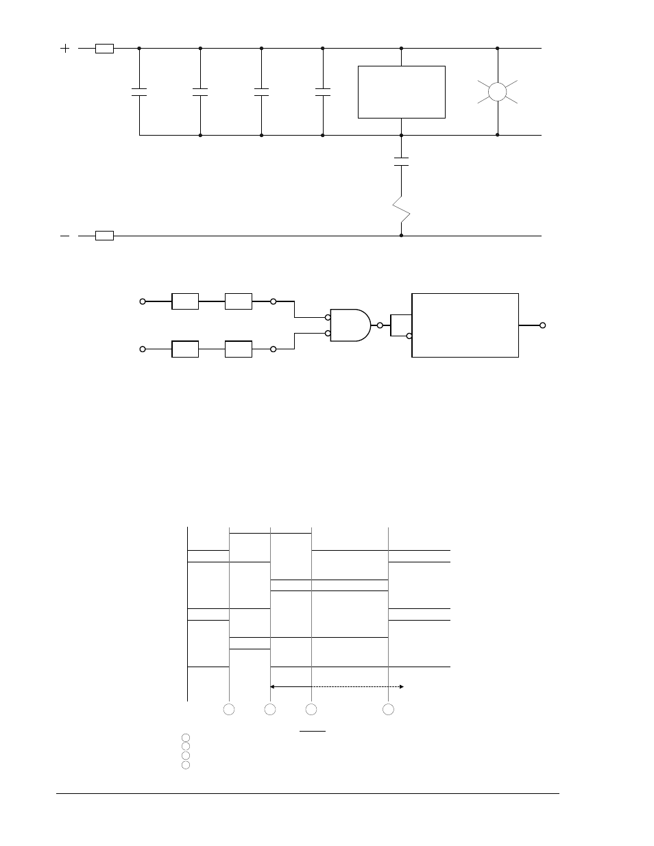
Figure 2-8. Trip Circuit Monitor Schematic Diagram
Figure 2-9. Trip Circuit Monitor Logic Diagram
When the breaker is closed, the trip bus T, is at negative potential through the low impedance path of the
trip coil and the TCM senses logic 1. Figure 2-10 illustrates the timing of this logic. When a trip occurs, the
trip bus is at positive potential, the voltage across the TCM is shorted, and it senses logic 0. When the
breaker opens, the 52a contact is series with the trip coil opens, the protective relay drops out, the trip
bus is at positive potential through the high impedance of the sensing element or the indicating light (if
used), and the TCM continues to sense a logic 0. The breaker status input (IN1) in the logic diagram is
used to block the function while the breaker, and therefore, the trip circuit are open. The timer is used to
prevent an alarm output during the transition between the closed and open states.
Figure 2-10. Trip Circuit Monitor Timing Diagram
86
Breaker
Retrip
O5
IOIT
21
IN2 (TCM)
Trip Ckt 1 Sense
P
T
52a
52TC1
N
D2822-06
T4
AN
D
ICS
ICS
LI1
LI2
I1
I2
O6
IN1
IN2
52b
Trip Circuit
Monitor
DELAY TIMER
START
RESET
OUT
T4
LT4
D
28
22
-0
7
08
-0
7-
98
A
LEGEND
Fault occurs, TCM shorted by Line relay
21
Protective Relays
Breaker opens, trip circuit opened
TCM
Trip Circuit Monitor
Relay drops out, trip bus floating
O6
TCM Timer Start
Breaker closed
T4
TCM Timer
Delay Time
21
52a
52b
TCM
O6
T4
D2822-08
08-07-98
A
B
C
D
B
C
D