Timer log, Timer log -35 – Basler Electric BE1-BPR User Manual
Page 87
9272000990 Rev J
BE1-BPR Functional Description
4-35
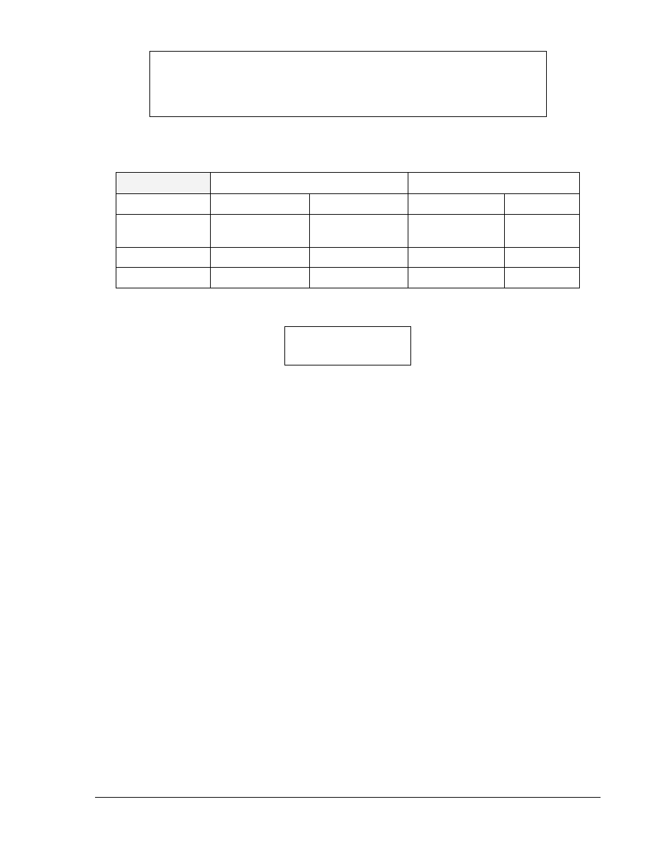
Breaker information used in the breaker resistor diagnostics is programmed using the BKRRES
command. If MAXOPS is programmed to zero, the resistor heating diagnostic is disabled.
BKRRES
Breaker resistor monitoring data
HMI Menu Branch: 3
Parameter
Unit of Measure
Range
Increment
Default
MAXOPS
breaker
operations
0 to 10
1
00,000
reset
minutes
0 to 255
1
0
Ires
primary amperes
0.000 to 6.8E38
0.001
0.000E+00
BKRRES HMI Screen Example:
BKRRES Command
Purpose:
Read or change breaker resistor monitoring data.
Syntax:
BKRRES[=<MAXOPS>,<reset>,<Ires>]
Comments:
An access area 1 or 3 password is required to change settings.
BKRRES Command Example:
Set Ires at 500 amperes, reset_time at 15 minutes, and MAXOPS at 4.
BKRRES=4,15,500
Timer Log
The timer log provides timing diagnostics to aid in evaluating the relay settings or external timing. Logs for
the last 40 events are stored in volatile memory. A log stores the time remaining on a timer/counter when
the logic programmed for the timer log alarm, using the PTLOG command, becomes true (an event).
PTLOG alarm logic is programmable using simple Boolean AND logic. Appropriate values must be
chosen for the logic variables in order for the time recorded to correspond to the timing diagnostic
desired.
A margin log is a typical timing diagnostic. A delay timer is typically used to delay the breaker failure
output (BFO) until sufficient time has elapsed for the primary protection scheme to operate. The time left
on the timer when the BF logic is cleared is the margin value (refer to Section 1 for a detailed timing
diagram discussion and illustration). Knowing the time remaining on that timer provides feedback on the
suitability of the time delay and margin allowed for the protection scheme to operate. If there is a large
discrepancy between the calculated and actual margin, corrective action can be taken before a problem
occurs.
Other timers may be set to measure some other parameter at the operator's discretion.
Use the PDIAG command to configure the timer log to set O14 or O15 (the software diagnostic alarm
outputs), if the timer value recorded is less than or greater than a programmed alarm value. A separate
alarm time can be set for each timer using the PTLOG command through the communications port. O14
or O15 can then be used to drive an output such as the ALARM output in order to provide an immediate
indication of a potential problem. The operator, upon receiving the alarm signal can query the relay
through the communication port or look at the DIAG screen in the RELAY STATUS MENU to identify the
NOTE
If Ires is programmed, then the DUTY LOG uses that value in current (I)
calculations instead of (CTP∗I[p][n]) because it would be difficult to separate the
arcing current from the fault current prior to the resistor being inserted.
BKROPS RESOPS
00036 0 OF 0