Rs-485 connections, Communication settings, Setup – Basler Electric BE1-BPR User Manual
Page 153: Rs-485 connections -13, Communication settings -13, Setup -13, Table 7-3. rs-485 pinouts (port1b)
9272000990 Rev J
BE1-BPR Installation
7-13
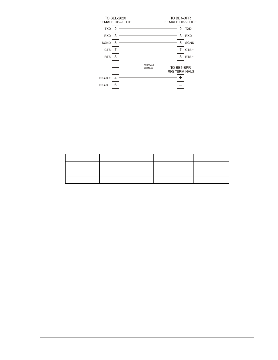
Figure 7-15. SEL-2020 Communications Processor to BE1-BPR (Straight Cable)
RS-485 Connections
The RS-485 connections are located on a terminal block shared with the IRIG-B terminals. The three RS-
485 terminals will mate with a standard communication cable. A twisted-pair cable is recommended.
Connector pin numbers, functions, names, and signal directions are shown in Table 7-3. A cable
connection diagram is provided in Figure 7-16.
Table 7-3. RS-485 Pinouts (Port1B)
Terminal
Function
Name
Direction
A
Send/Receive A
(SDA/RDA)
In/Out
B
Send/Receive B
(SDB/RDB)
In/Out
G
Signal Ground
(GND)
N/A
Communication Settings
Communication settings are the formal set of conventions controlling the format and relative timing of
message exchange between two communications terminals. Relay settings are stored as RATEDPS,
where RATE = baud rate (300 to 19.2k), D = number data bits (7 or 8), P = parity (O, E, or N), and S =
stop bits (1 or 2). The default protocol is 96008N1.
Setup
To initially prepare the relay for communications, go to the MAINTENANCE menu and set the proper
settings for the front and rear port or use the COMx command through the communication port with the
initial settings set for the proper mode as shown in the front panel maintenance menu.