Reclosing functions, Preprogrammed logic description, Breaker failure logic 1 for standard relays (bfl1) – Basler Electric BE1-BPR User Manual
Page 36: Reclosing functions -12, Preprogrammed logic description -12, Figure 2-15. reclosing logic circuit
2-12
BE1-BPR Application
9272000990 Rev J
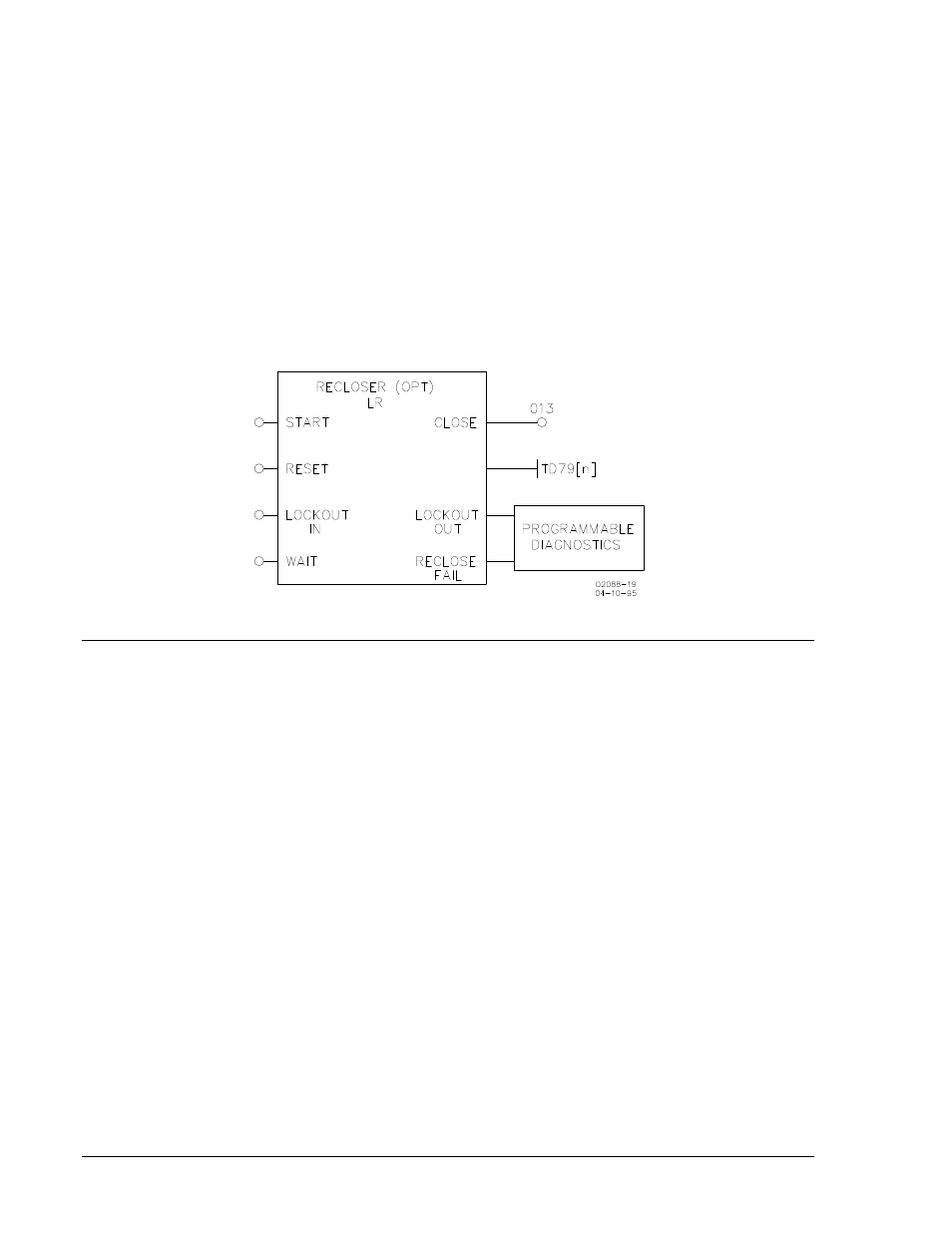
Reclosing Functions
A Reclosing Function is available in the BE1-BPR relay that can operate in parallel with the breaker
failure logic. All inputs are programmable using the BESTlogic LR command. When reclosing is enabled,
output 13 (O13) is designated at the reclose (close) output and can be connected to any physical output
by using the LO command. Three reclosing shots are available.
Separate time delays are programmable through the front panel or serial port by using the TD79
command. Time delay settings are available for each shot (TD791, TD792, and TD793), for the reset
timer (TD79R), reclose fail timer (TD79F) and a maximum reclose cycle timer (TD79M). Lockout and
reclose fail diagnostic flags are set/reset by the programmable diagnostics. Use the PDIAG command to
program separate outputs for lockout and reclose fail. The reclosing state (RESET, WAIT, TIMING, or
LOCKOUT) can be viewed from the front panel recloser status screen in the relay status menu or by
using the STATUS command.
There are four reclose function inputs, three available outputs, and one mode programmable feature
(TYPE). The inputs and outputs are shown in Figure 2-15.
Figure 2-15. Reclosing Logic Circuit
PREPROGRAMMED LOGIC DESCRIPTION
BE1-BPR relays are factory programmed with protection schemes that provide breaker failure protection
for most systems. These preprogrammed breaker failure logic schemes are described in the following
paragraphs. The programmable logic equations are not provided in this description. See Section 5,
Programmable Logic, for information on the description and use of the programmable logic as well as
application hints for programming custom logic.
Breaker Failure Logic 1 for Standard Relays (BFL1)
BFL1 logic (shown in Figure 2-16) provides the following application features.
1. Three-Pole Tripping BF Logic (No input or output latch-in provided). Three BFI inputs are available at
IN3, IN4, and IN5 to start delay timer T1. If the BFI inputs are not reset by the time timer 1 times out
and either the phase (F1) or neutral (F2) fault detector is picked up, then BFO1 and BFO3 will close
(OUT1 and OUT3), tripping the backup breakers. Refer to the breaker failure timing diagram in
Section 1 for information on setting the delay timer.
2. No Current BF Logic (No input or output latch-in provided). Some faults may not provide current to
the CTs (i.e. internal transformer failures). In that case two additional BFI inputs are available (IN6
and IN7) to start delay timer T2. These inputs are not supervised by a fault detector. If the BFI input is
not reset by the time the timer times out, BFO2 (OUT2) will close tripping the backup breakers. Refer
to the breaker failure timing diagram in Section 1 for information on setting the delay timer.
3. Trip Coil Status Monitor. Preprogrammed logic is provided using IN1 to provide breaker status and
IN2 for trip coil continuity. Refer to Application Data in this section for further details on the circuit
operation.
4. Breaker Arc Protection. Preprogrammed logic is provided using fault detector 3 (F3) for the MAF fault
detector, IN1 for breaker status, and OUT4 for the arc detector output. Refer to Application Data in
this section for further details on the circuit operation.