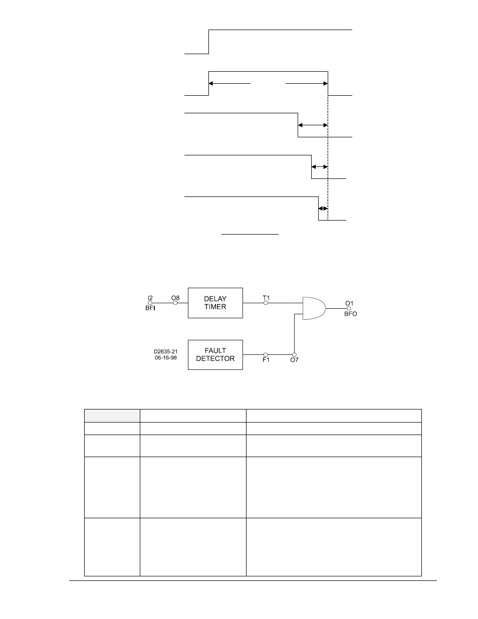
Figure 4-11. margin log timing sequence, Figure 4-12. margin log logic – Basler Electric BE1-BPR User Manual
Page 89
9272000990 Rev J
BE1-BPR Functional Description
4-37
Figure 4-11. Margin Log Timing Sequence
Figure 4-12. Margin Log Logic
PTLOG
Timer log and alarm log
HMI Menu Branch: N/A
Parameter
Range
Comments
logic term
N/A
AND and NOT(/) logic variables can be used to
specify when timer log is triggered.
alm_type
H, L, or 0
H: Alarm occurs when the remaining time at the
point the timer logic becomes true is higher than
the alarm_time setting.
L: Alarm occurs when logic becomes true inside
the alm_time margin.
0: Disables the alarm function.
alm_time
0 - 65 seconds
A diagnostic alarm is logged if logic becomes
true inside (alm_type L) or outside (alm_type H)
this time window. alm_time units can be
milliseconds (default), seconds (s), or cycles (c).
Figure 4-13 illustrates an example of an H alarm
and L alarm condition.
I2
TD1
100 msec.
25 msec.
O7
17:00:00.000
05/01/98
13 msec.
O7
18:00:00.000
05/01/98
ASCII TIMER LOG
TLOG1= 8m* 19:00:00.000 05/01/98
TLOG1= 13m 18:00:00.000 05/01/98
TLOG1= 25m 17:00:00.000 05/01/98
8 msec.
O7
19:00:00.000
05/01/98
D
26
35
-1
3
05
-0
5-
98