Application of fault detectors – Basler Electric BE1-BPR User Manual
Page 28
2-4
BE1-BPR Application
9272000990 Rev J
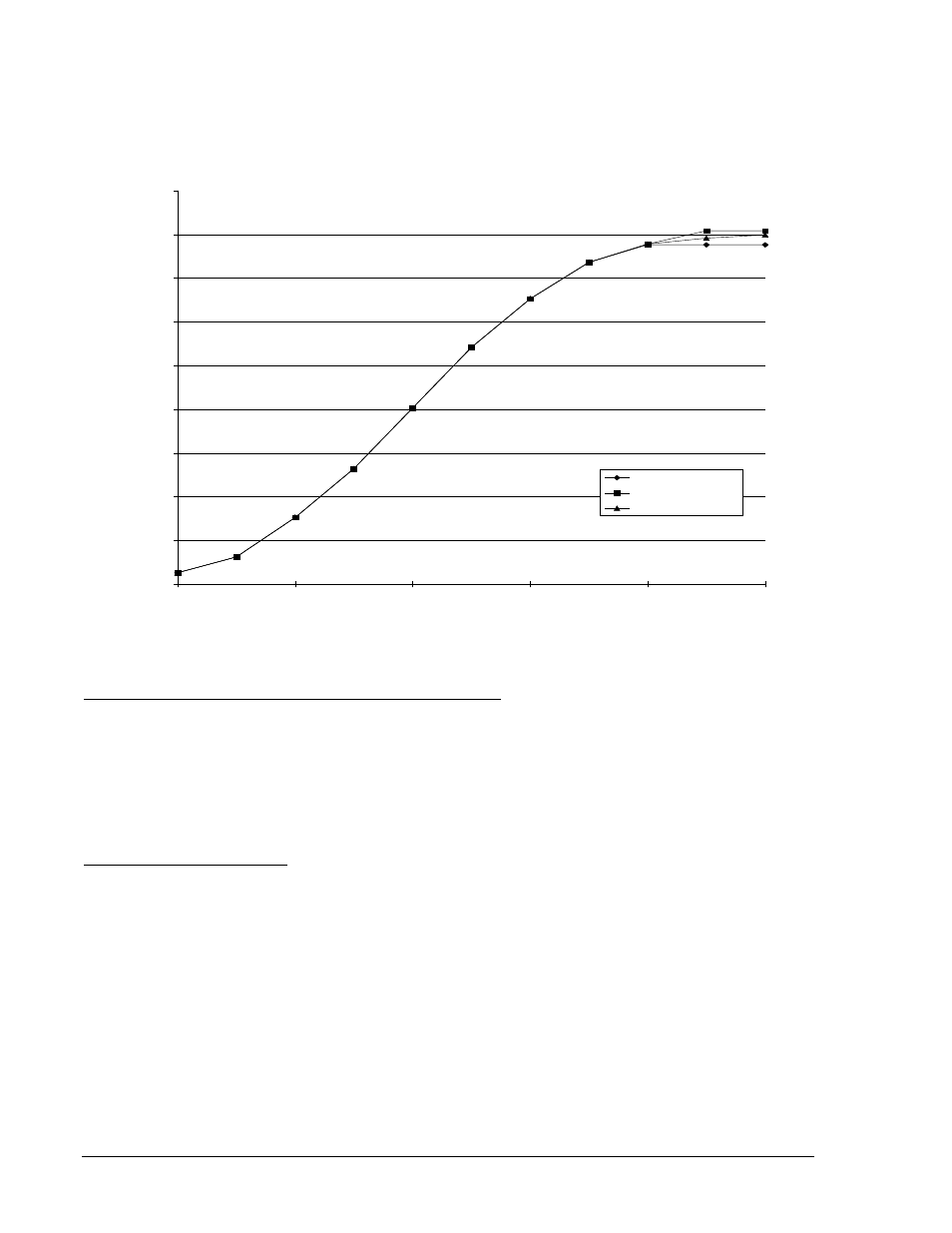
This MAF fault detector is programmed by setting the fault detector digital filter selection to 2 (DFLTR2).
For the MAF fault detector to pickup (or dropout), the rms value of the average of the last 'n' cycles of
current must be above (or below) the pickup setting. Typically, this filter is slow to pickup and slow to
dropout but it is intended for use in low current applications where speed is not critical.
Figure 2-4 shows maximum dropout timing versus current input levels for a 10 cycle MAF fault detector.
Figure 2-4. Maximum Dropout Timing with 10 Cycle MAF Fault Detector
This fault detector has the same characteristics as the Type 1 instantaneous fault detector with the
exception that all three phases must be picked up before the fault detector will pickup. This fault detector
can be used in BF logic schemes and is programmed by setting the fault detector logic (LF) type to PI
(phase overcurrent) and the digital filter selection to 3.
Three-Phase Fault Instantaneous (50) Fault Detector Type 3
A 3-phase fault is the worst case fault for system stability and requires fast clearing times with small
margins. A 3-phase fault detector and a separate timer could be used in addition to the 3-phase fault
detector and timer to allow BF protection for both worst case faults and normal faults.
Phase and Ground Instantaneous Fault Detectors. Normally, it is adequate to monitor the three phase
currents as they represent the current in the poles of the protected breaker. However, if the sensitivity of
the ground relays is significantly higher than the sensitivity of the phase relays, it may be desirable to
apply a ground fault detector so that you can be assured that the breaker failure protection will pickup for
any fault that is sensed by the initiating relays. Each fault detector can be independently set to monitor
either the three phase current inputs or the neutral current input. Fault detector F1 is programmed as a
phase instantaneous fault detector and fault detector F2 is programmed as a neutral instantaneous fault
detector in all of the preprogrammed logic schemes.
Application of Fault Detectors
Three-Phase Instantaneous Fault Detectors. For system stability, a three-phase fault is the worst case.
The dynamic stability of the system is not affected as much by the other fault combinations. Since three-
phase faults are generally rarer than the other fault combinations, it may be desirable to enhance security
by treating three-phase faults differently. One of the fault detectors can be set up as a PI, 3 (phase
current, Type 3) fault detector to supervise a timer set at the three phase fault, dynamic stability limit. The
normal timer supervised by the other fault detectors would then be set with a longer time delay (with more
margin) set at the two phase and ground fault (the next worst case), dynamic stability limit.
20
40
60
80
100
120
140
160
180
200
1.05
1.25
2
5
20
40
MULTIPLES OF PICKUP BEFORE DROPOUT
M
A
X.
D
R
O
PO
U
T
TI
M
E
(m
s)
PU=1.00A, 10 CYC
PU=0.50A, 10 CYC
PU=0.05A, 10 CYC
PU=1.00A, 10 CYC
PU=0.50A, 10 CYC
PU=0.05A, 10 CYC
D2838-24