Breaker resistor protection, Breaker resistor protection -10, Figure 2-12. breaker arc detector circuits – Basler Electric BE1-BPR User Manual
Page 34: Figure 2-13. breaker resistor protection circuits
2-10
BE1-BPR Application
9272000990 Rev J
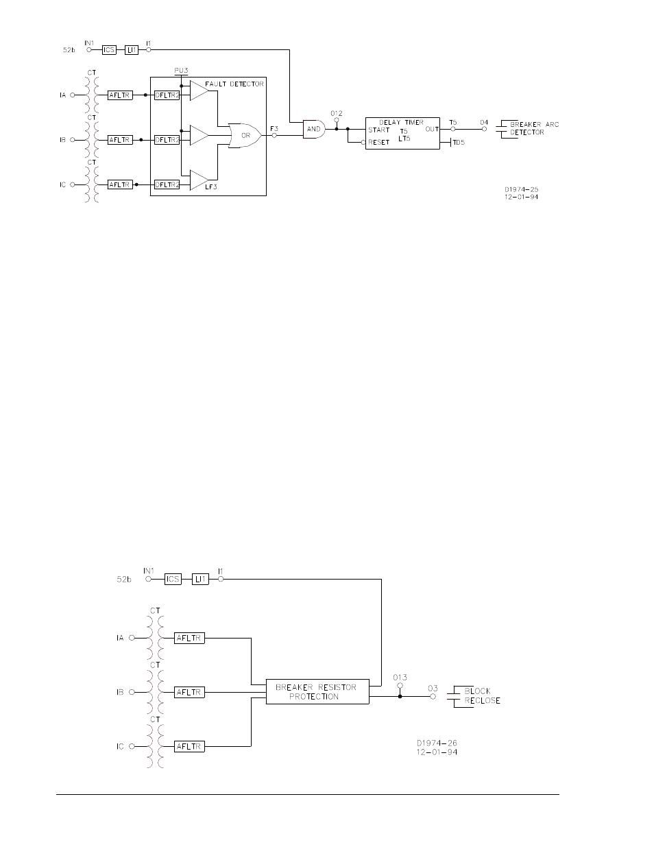
Figure 2-12. Breaker Arc Detector Circuits
The breaker arc detector logic employed in the preprogrammed schemes logically ANDs the MAF fault
detector (F3) and the 52b input (I1) to start a delay timer (T5). Timer delay can be as long as 60 seconds.
The timer delay should be set to 1.5 to 2.0 times the MAF window time. Both the fault detector and
breaker status must stay unchanged for the entire length of the time delay or the timer is reset. If the timer
does time out, the breaker arc output (O4) closes. This output could be used to reclose the breaker,
extinguish the arc, prevent secondary circuit switcher failure, externally parallel the BFO, or to give an
alarm.
Breaker Resistor Protection
Breaker resistor protection is a BE1-BPR relay feature that monitors the number of times a breaker
opening resistor has been used and the amount of elapsed time between operations. If additional
openings (operations) would exceed the resistor maximum power rating, the breaker resistor protection
feature operates output 13 (O13), which can be used as a block reclose output. Breaker resistors are
typically rated to handle X operations (i.e. - 5 operations) in T time (i.e. - 15 minutes cooling time for each
operation). The resistor protection is a self contained module (Figure 2-13) that counts and time tags each
operation then decrements the count T time after it occurred. If the count reaches the limit, an internal
output becomes TRUE. In the enhanced logic schemes, the programmable logic output (O13) drives the
block reclose output. (If a reclosing function is enabled, programmable logic output (O13) is driven by the
reclose output, and the block reclose signal is internally ORed with the defined reclose WAIT logic input.)
This output is intended to block reclosing until the count has dropped below the limit. This action allows
the resistors to cool sufficiently and protects the opening resistors.
Refer to Output Contacts in this section for additional information if your requirements call for a NC
contact for this purpose. Also see Section 4, Functional Description, for a detailed functional description
on how to program the resistor protection function module.
Figure 2-13. Breaker Resistor Protection Circuits