Super Systems 20PQ User Manual
Page 15
11
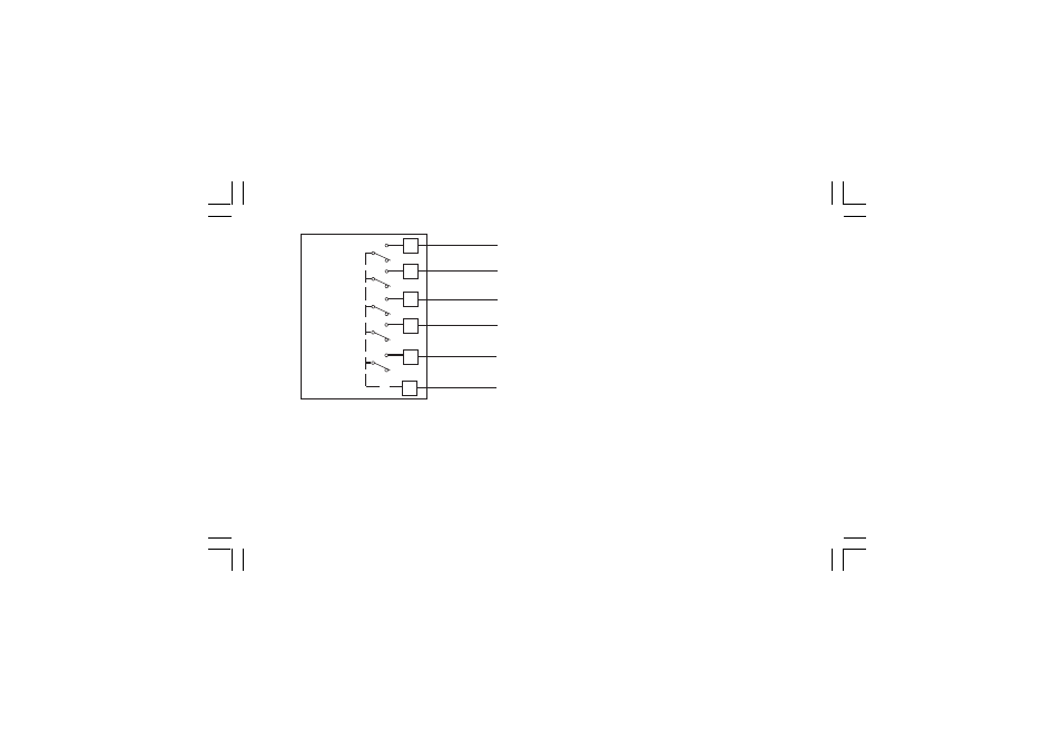
Fig. 11.C RELAY OUTPUTS 15 to 19 WIRING
The outputs from OUT 10 to 19 are equipped with relays having
contact rating equal to 0.5A/250V AC on resistive load.
GENERAL NOTES ABOUT RELAY OUTPUT WIRING
1) To avoid electrical shock, connect power line at the end of
the wiring procedure.
2) For power connections use No 16 AWG or larger wires rated for
at last 75 °C.
3) Use copper conductors only.
4) Don’t run input wires together with power cables.
For all relay outputs, the number of operations is 1 x 10
5
at
specified rating.
All relay contacts are protected by varistor against inductive load
with inductive component up to 0.5 A.
The following recommendations avoid serious problems which
may occur, when using relay output for driving inductive loads.
INDUCTIVE LOADS
High voltage transients may occur switching inductive loads.
Through the internal contacts these transients may introduce
disturbances which can affect the performance of the instru-
ment.
For all the outputs, the internal protection (varistor) assures a
correct protection up to 0.5 A of inductive component.
OUT 15
50
NO OUT 15
51
NO OUT 16
NO OUT 17
52
53
NO OUT 18
54
NO OUT 19
55
COMMON
OUT 16
OUT 17
OUT 18
OUT 19
COMMON
XKP-1-C2.p65
10/30/01, 9:36 AM
11