Super Systems 20PQ User Manual
Page 34
30
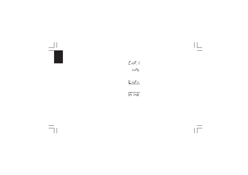
CnF. 1
specific instrument configuration (i.e. setting OUT 3 different
from servo, all the parameters related to servomotor output
will be skipped).
2) During configuration parameters modify mode, the upper
display shows the selected parameter group, the lower
display shows the mnemonic code of the selected parameter
while the central display shows the value or status assigned
to the selected parameter.
3) For an easy consultation of this manual, a sheet named
"Reference parameter guide" with all the parameter
visualizations is enclosed.
The group (column) of configuration parameters are identified
by the "C" letter followed by A, b, etc.
The "code" formed by the column and row (example [C.d03])
is reported, in the user manual, before each parameter
description and allows you to quickly find out the respective
parameter.
When it is desired to exit from configuration modify mode
proceed as follows:
a) Push "MENU" push-button until the "Configuration group END
is displayed.
b) Pushing ”
s” or “t” push-button select the "YES" indication.
c) Push “MENU” push-button. The instrument terminates the
configuration modify mode, it preforms an automatic reset
and restarts in the run time mode.
CONFIGURATION GROUP 1 [C.dxx]
MAIN AND AUXILIARY INPUT CONFIGURATION
Push the FUNC push-button
- Line frequency - [C.d01]
Range: 50 Hz
60 Hz
- Main input type and range - [C.d02]
Ranges:
* 1 = TC L
From -100 to
900
°C
* 2 = TC J
From -100 to 1000
°C
* 3 = TC K
From -100 to 1370
°C
* 4 = TC T
From -200 to
400
°C
* 5 = TC U
From -200 to
600
°C
* 6 = TC E
From -100 to
800
°C
7 = TC N
From -100 to 1400
°C
XKP-1-C2.p65
10/30/01, 9:37 AM
30