Relay assignments, Elay, Ssignments – Super Systems 9205 Series User Manual
Page 106
Series 9205 Operations Manual Rev A
105
Source 2 This assigns the second thermocouple that will be compared. The options are:
Not used
Instrument 1-27
n/a
Input 3
Input 2
Input1
Source 3 This assigns the third thermocouple that will be compared. The options are:
Not used
Instrument 1-27
n/a
Input 3
Input 2
Input1
Tolerance Band This allows the operator to set the tolerance band between the thermocouples being
compared. The range is -9999 to 9999.
Source 2 Offset This allows for an offset to be assigned to the second thermocouple and taken into account
when the comparison between values is made. The range is -9999 to 9999.
Source 3 Offset This allows for an offset to be assigned to the third thermocouple and taken into account
when the comparison between values is made. The range is -9999 to 9999.
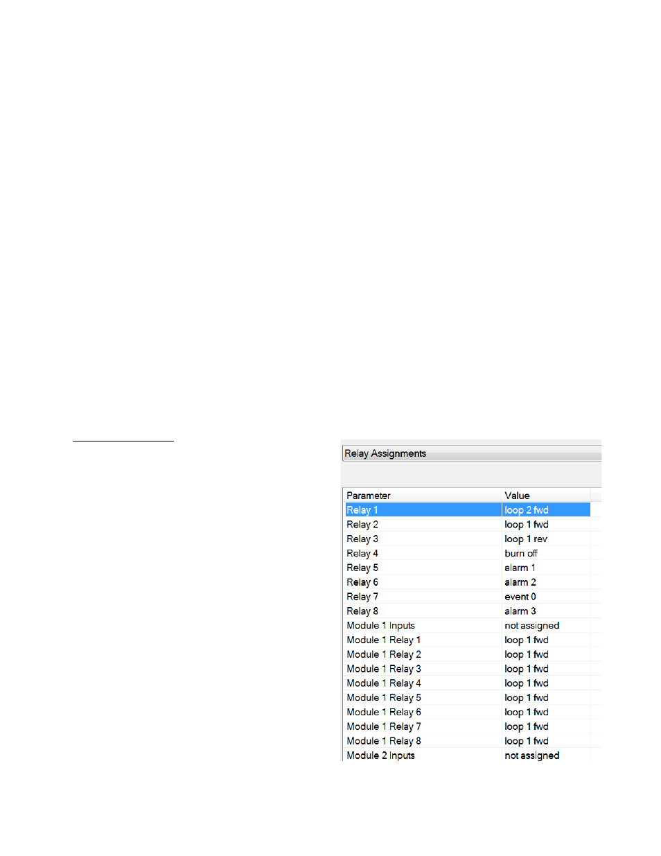
Relay Assignments
The 9205 controller has the option of using eight relay
outputs. All of the relays have a positive common
terminal and independent negative terminals. All of
the relays are configured in a normally closed
position except relay number eight, which has both a
normally closed (NC) and a normally open (NO)
terminal. These relays can be configured to work
with events, alarms, loops, burnoff and alarm
combinations.
Relay Output Terminals
Relay Output 1 – terminals 7 and 8
Relay Output 2 – terminals 7 and 9
Relay Output 3 – terminals 7 and 10
Relay Output 4 – terminals 7 and 11
Relay Output 5 – terminals 7 and 12
Relay Output 6 – terminals 7 and 13
Relay Output 7 – terminals 7 and 14
Relay Output 8 – terminals 7 and 15 NC
Relay Output 8 – terminals 7 and 16 NO