Generic instrument setups, Configure generic instruments, Eneric – Super Systems 9205 Series User Manual
Page 125: Nstrument, Etups
Series 9205 Operations Manual Rev A
124
Generic Instrument Setups
The generic instrument’s data will be stored in
certain registers on the host instrument, such
as the 9205 controller. Each instrument is
allotted a certain set of registers, starting with
register 1000. To determine the beginning
register, use the following calculation: (100 *
generic instrument’s number (1 – 16)) + 900.
Therefore, instrument 1 would begin at
register 1000: (100 * 1) + 900. Instrument 7
would begin at register 1600: (100 * 7) + 900. Each instrument is allotted 100 registers, therefore,
instrument 1’s allotment is from register 1000 to 1099 on the 9205 controller, instrument 2’s allotment is
from register 1100 to 1199 on the 9205 controller, etc.
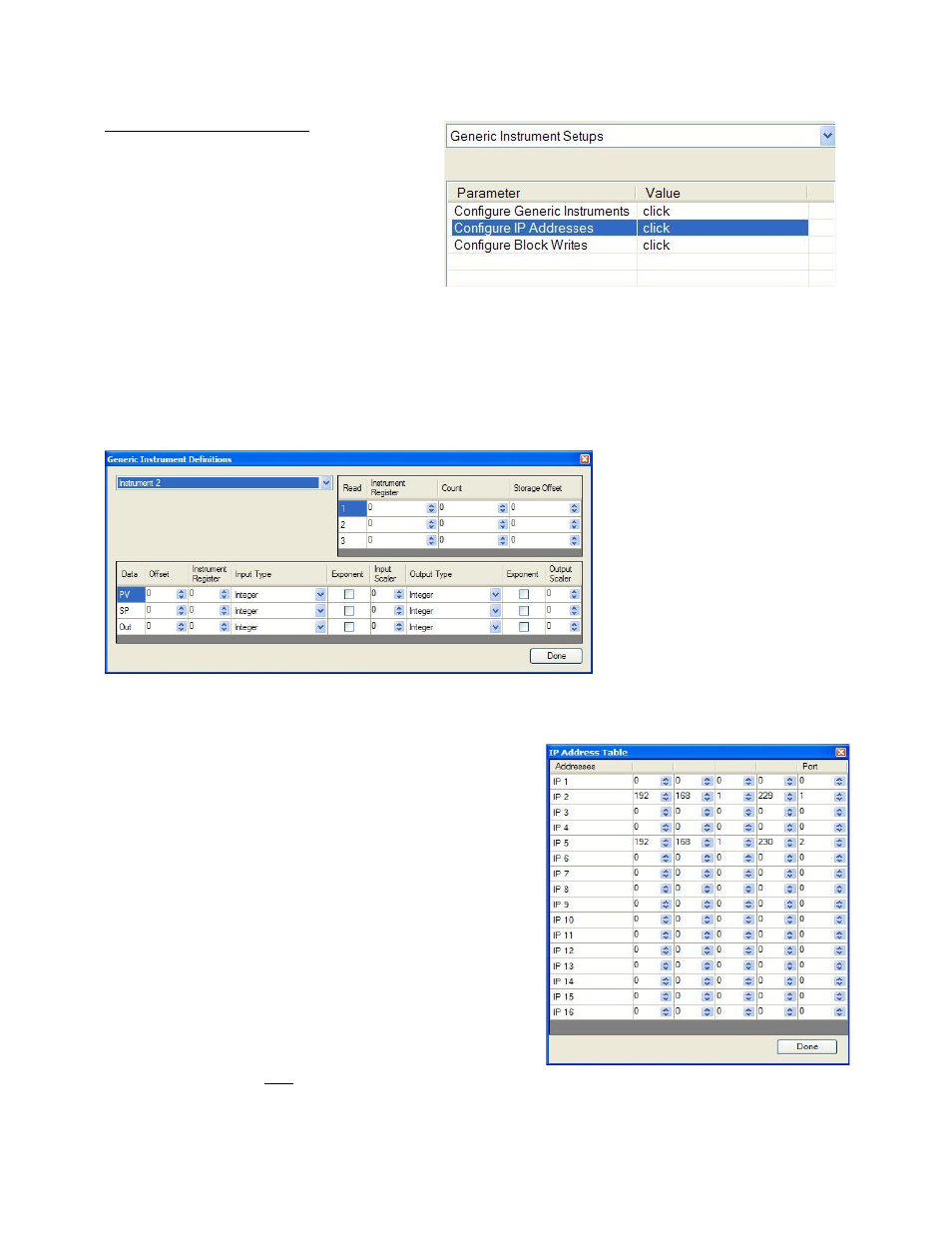
The
Generic Instrument Setups
menu is split into three parts: Configure Generic Instruments, Configure IP
Addresses, and Configure Block Writes.
Configure Generic Instruments
This screen is where the user can
configure the main sections for
each generic instrument. The
drop-down box in the top left will
select the generic instrument to
set up. The options are:
Instrument 1 – Instrument 16.
The three reads can be set up in
the grid in the top of the form.
The Instrument Register field will
be the register in the 9205
controller. The range is 0 – 32767.
The Count field will be the number of successive registers to read. The range is 0 – 100. The Storage Offset
field will be the offset in the generic instruments registers (1000 – 1099 for Instrument 1, 1100 to 1199 for
Instrument 2, etc). The range is 0 – 99.
The setup for the PV (Process Variable), SP (Setpoint), and
Out (Output) can be done in the grid in the bottom of the form.
The Offset field is the instrument’s offset. The range is 0 –
32767. The Instrument Register field is the register in the
9205 controller. The range is 0 – 32767. The Input Type field
will determine what kind of type the value will be. The
options are: Integer, Big Endian, Big Endian Byte Swap, Little
Endian, or Little Endian Byte Swap. The Exponent field will
determine if there is an exponent value. Checking the
checkbox will indicate that the Scaler is a power of 10. The
Input Scaler field can then be a positive or negative value in
the range -31 to +31. The Output Type will determine what
kind of the output value will be. The options are: Integer, Big
Endian, Big Endian Byte Swap, Little Endian, or Little Endian
Byte Swap. The Exponent field will determine if there is an
exponent value. Checking the checkbox will indicate that the
Scaler is a power of 10. The Output Scaler field can then be a
positive or negative value in the range -31 to +31.
NOTE:
Exponent values affect only floating point values.