Analog input setup, Nalog, Nput – Super Systems 9205 Series User Manual
Page 109: Etup
Series 9205 Operations Manual Rev A
108
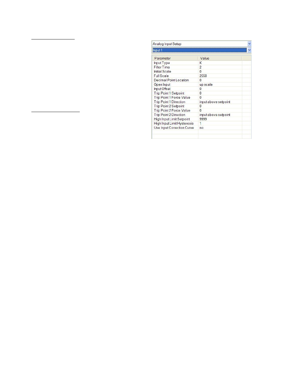
Analog Input Setup
The 9205 controller has three analog inputs. Each of the
inputs comes with a factory default configuration
dependent on the application. It can be modified prior
to shipment to your facility or in the field by a technician
or qualified/trained person with the proper security
code. Before connecting your input source to the
terminals, please verify that the input type is set up
correctly. If the Input Type is not correct, do not connect
the input source to the terminals, as damage can occur.
Please consult SSi by calling (513) 772-0060 before
making any changes.
Analog Input Terminals
Analog Input 1 – terminals 31 and 32
Analog Input 2 – terminals 29 and 30
Analog Input 3 – terminals 27 and 28
Input Type
The thermocouple type for most applications can be modified depending on your specific needs.
Note:
Some of the inputs DO NOT allow the user to modify the Input type
. To change the Input type, first select
which input you want to change by selecting it in the pull-down menu just below the main menu list.
Clicking on the Value will display an input box, and then you can use the pull-down menu to select the
desired parameter. Once selected, click
OK
and the displayed Input type under Value will be the current
type. The following is a list of the options:
B
S
12.5 volts **
C
T
781.25mv
E
2.5 volts
195.3125 mV
J
1.25 volts
K
78.125 mV
N
19.53125 mV
NNM
4-20 mA **
R
25 volts **
** - When the specified input type is selected, a jumper located inside the case will need
to be placed on that specific input for reading this selection. If jumper is not placed on
input, then damage could occur to the board.
Filter time
The filter time is a factory applied averaging tool used to help maintain steady control in high EMI
environments. The filter time should not be adjusted with consulting SSI. Clicking on this value will display
an input box from which the user can select a new value. The range is 0 to 32767.
Initial Scale
This is the initial scale value. This could also be referred to as the starting value. For example, the initial
value is the value when 0 volts is on the selected input; or on a 4-20 mA input, it would be the value at the
selected input of 4 mA. Clicking on this value will display an input box from which the user can select a new
value. The range is –32768 to 32767.
Full scale
This is the full scale value. Clicking on this value will display an input box from which the user can select a
new value. The range is –32768 to 32767.