Analog output setup, Nalog, Utput – Super Systems 9205 Series User Manual
Page 111: Etup
Series 9205 Operations Manual Rev A
110
High Input Limit Hysteresis
This is the hysteresis for the high input limit. The hysteresis cannot be assigned any value above this. The
range is –32768 to 32768.
Use Input Correction Curve
This option will allow the user to use a correction curve on the input. The options are No or Yes.
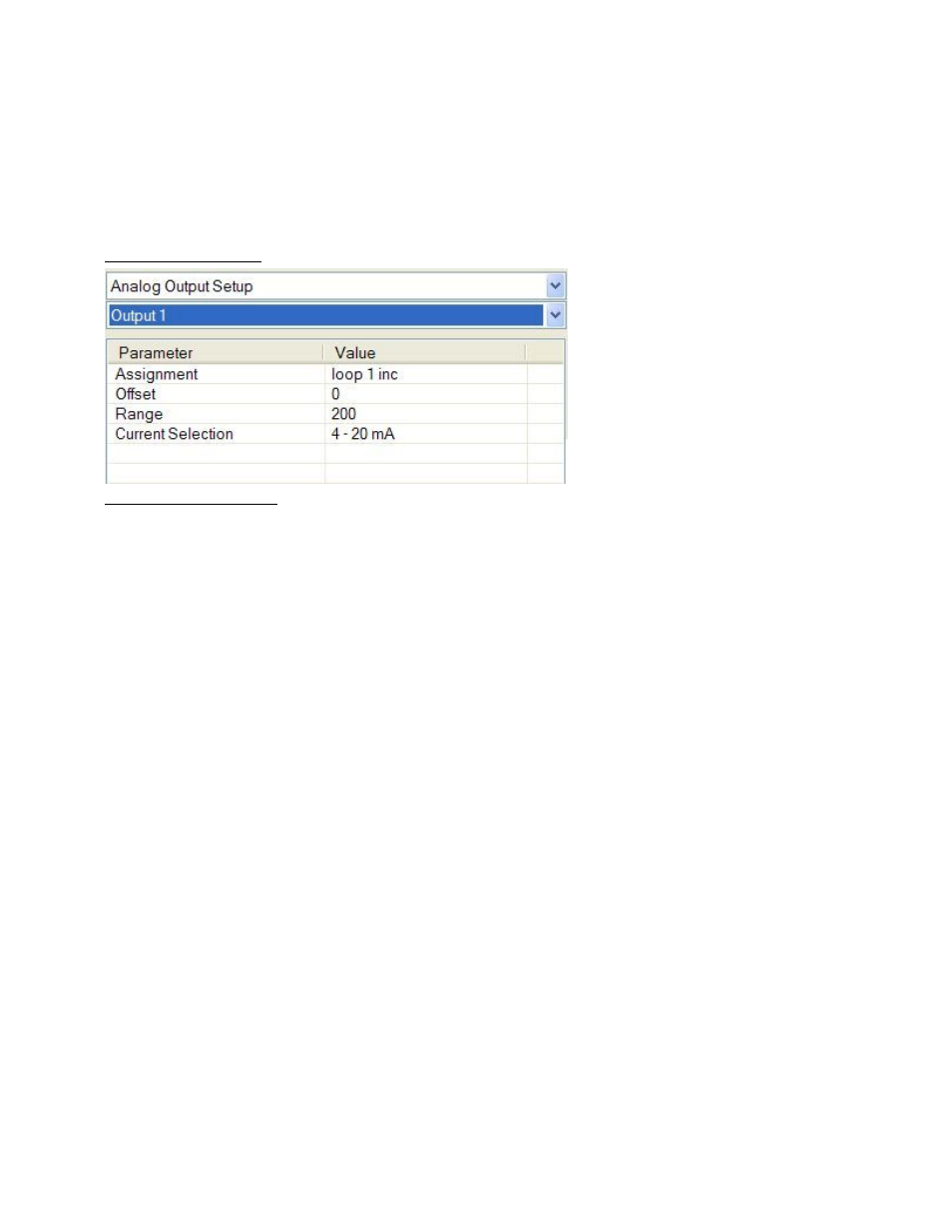
Analog Output Setup
The 9205 controller has the option of
six analog outputs. The outputs are
ranged for a 4 – 20 milliamp signal or
a 0 – 20 milliamp signal. Each output
comes with a factory default
configuration dependent on the
application. Each output can be
modified prior to shipment to your
facility or in the field by a supervisor.
Analog Output Terminals
Analog output 1 – terminals 24 and 25
Analog output 2 – terminals 25 and 26
Analog outputs 3, 4, 5, and 6 are enabled by use of an SSi QuadDAC board that connects to two RS485
terminals on the 9205 (terminals 5 and 6 for Slave 1, terminals 22 and 23 for Slave 2). Use the
Port Setup menu to configure communication parameters.
Assignment
The analog output assignment can be modified depending on your system requirements. To change the
Assignment first select which analog output you want to change by selecting it in the pull-down menu just
below the main menu. Clicking on this value will display an input box, and then you can use the pull-down
menu to select the desired parameter. Once selected, click OK
and the displayed assignment under Value
will be the current assignment type. The following is a list of the options:
PV 1 retrans
Loop 1 inc
Loop 1 dec
Loop 1 combo
PV 2 retrans
Loop 2 inc
Loop 2 dec
Loop 3 combo
PV 3 retrans
Loop 3 inc
Loop 3 dec
Loop 3 combo
Input 1 retrans
Input 2 retrans
Input 3 retrans
Not assigned
O2 offset log
SP1 retrans
SP2 retrans
SP3 retrans
Programmer ID run
Valve 1 SP
Valve 2 SP
Valve 3 SP
Valve 4 SP
Prog 1 Quench speed (0-1000=0-100%)
Programmer 1 DAC 1
Programmer 1 DAC 2
Programmer 1 DAC 3
Programmer 1 DAC 4
Programmer 1 DAC 5
Programmer 1 DAC 6
Prog 2 Quench speed (0-1000=0-100%)
Programmer 2 DAC 1
Programmer 2 DAC 2
Programmer 2 DAC 3
Programmer 2 DAC 4
Programmer 2 DAC 5
Programmer 2 DAC 6
Disabled
Combo example for carbon: 4 – 12 mA Air
12 – 20 mA Gas