Plc data mapping, Analog input correction curves, Instrument calculation – Super Systems 9205 Series User Manual
Page 129: Apping, Nalog, Nput, Orrection, Urves, Nstrument, Alculation
Series 9205 Operations Manual Rev A
128
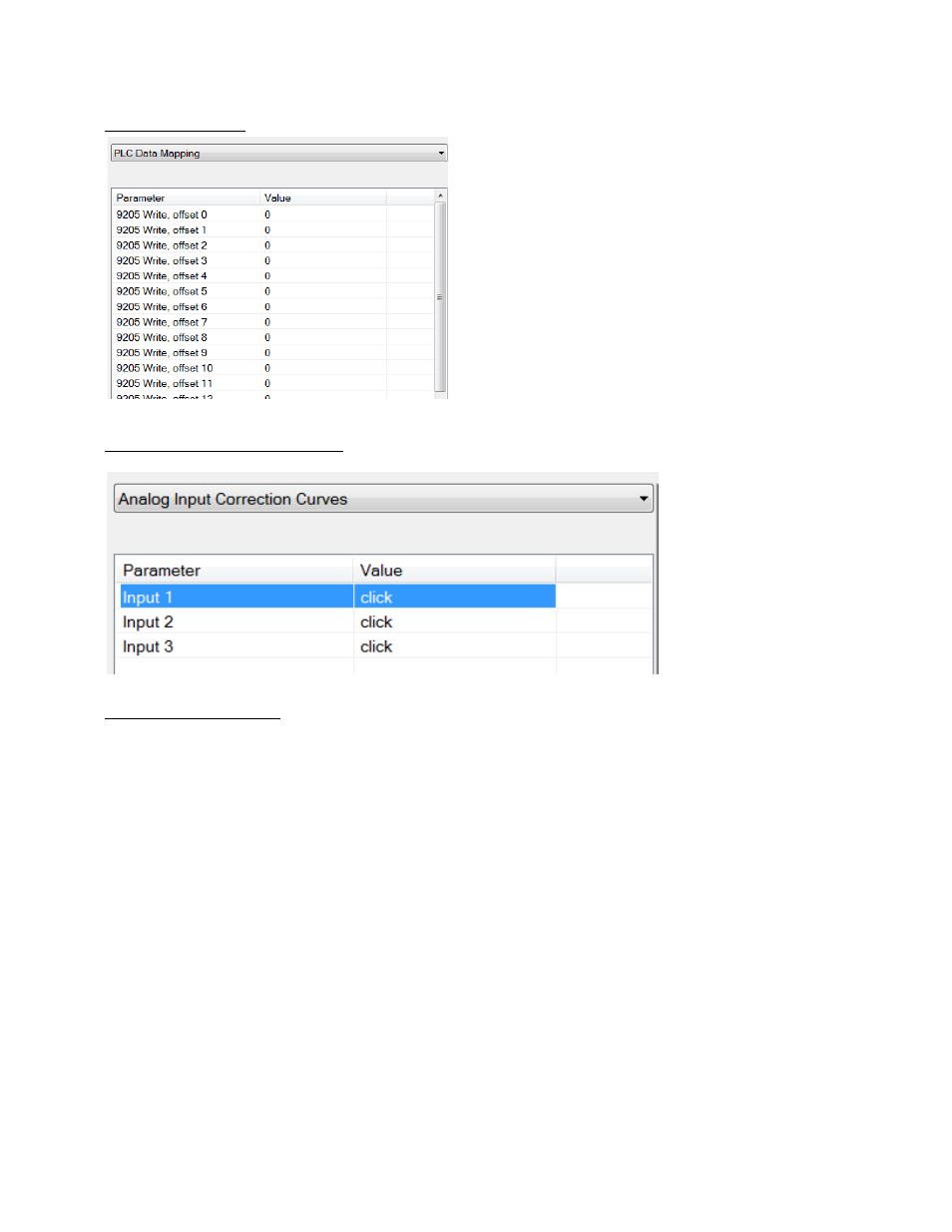
PLC Data Mapping
This option allows the user to custom map data from
registers inside the PLC to the registers in the
controller, and vice versa. The 9205 registers for
mapping use a hexadecimal number to decode, so
4100hex will get instrument 1 offset 0. 4101hex will get
an instrument 1 offset 1
NOTE: Convert the Hexadecimal value to Decimal value
before entering it into the 9205.
For example: 4400Hex is 17408 Decimal.
Analog Input Correction Curves
This option allows the
user to edit a curve on an
input 1,2, or 3 at a
specific temperature
point. Select the
appropriate curve and
Click to edit. Input the
temperature and the
error.
Instrument Calculation
The Instrument Calculation menu allows programming code-like lines to be executed at a variable time
interval per step.
Note – It is important to contact Super Systems at (513) 772-0060 before creating or
modifying any Instrument Calculation customization
.
General Description
The Instrument Calculation allows for fifty (50) lines of program and fifty (50) program variables. Program
variables allow for storage on intermediate results of calculations.
A program variable is designated by a v followed by a number from 0 to the number of variables – 1.
A Lower or Upper case “V” is valid, as well as leading zeroes. The following are all considered the same
variable: V3, v3, v0003.
The 9205’s Modbus registers can be used as input variables in the equations without restriction. To protect
the instrument, Modbus registers are restricted as output registers.
Modbus registers are designated by an upper or lower case “M” followed by a number.
Note – The standard Modbus routine is called to retrieve the Modbus variable, therefore a 0x8000 (-32768)
will be returned for an invalid register
.
Note – Modbus registers are stored with integer values, so adjustments will need to be made for decimal
values
.
If the instrument can have external analog input boards, or the instrument is a Video Recorder or DAQ,
these inputs can be accessed directly as A1 through A40. By using the “A” designation, the Modbus register