Furnace setup – Super Systems 9205 Series User Manual
Page 43
Series 9205 Operations Manual Rev A
42
Atm Zone Number
This option will allow the user to set the zone number for the assignment. The range is 0 – 5.
Atm Zone Offset
This option will allow the user to enter an offset for the assignment. The range is -4000 – 4000.
Temp Source
This will allow the user to set the temperature instrument for the zone assignment. The options are:
Loop 1
Instrument 5
Instrument 12
Instrument 19
Loop 2
Instrument 6
Instrument 13
Instrument 20
Loop 3
Instrument 7
Instrument 14
Instrument 21
Instrument 1
Instrument 8
Instrument 15
Instrument 22
Instrument 2
Instrument 9
Instrument 16
Instrument 23
Instrument 3
Instrument 10
Instrument 17
Instrument 24
Instrument 4
Instrument 11
Instrument 18
Instrument 25
Temp Zone Number
This option will allow the user to set the zone number for the assignment. The range is 0 – 5.
Zone Offset, Temp
This option will allow the user to enter an offset for the assignment. The range is -4000 – 4000.
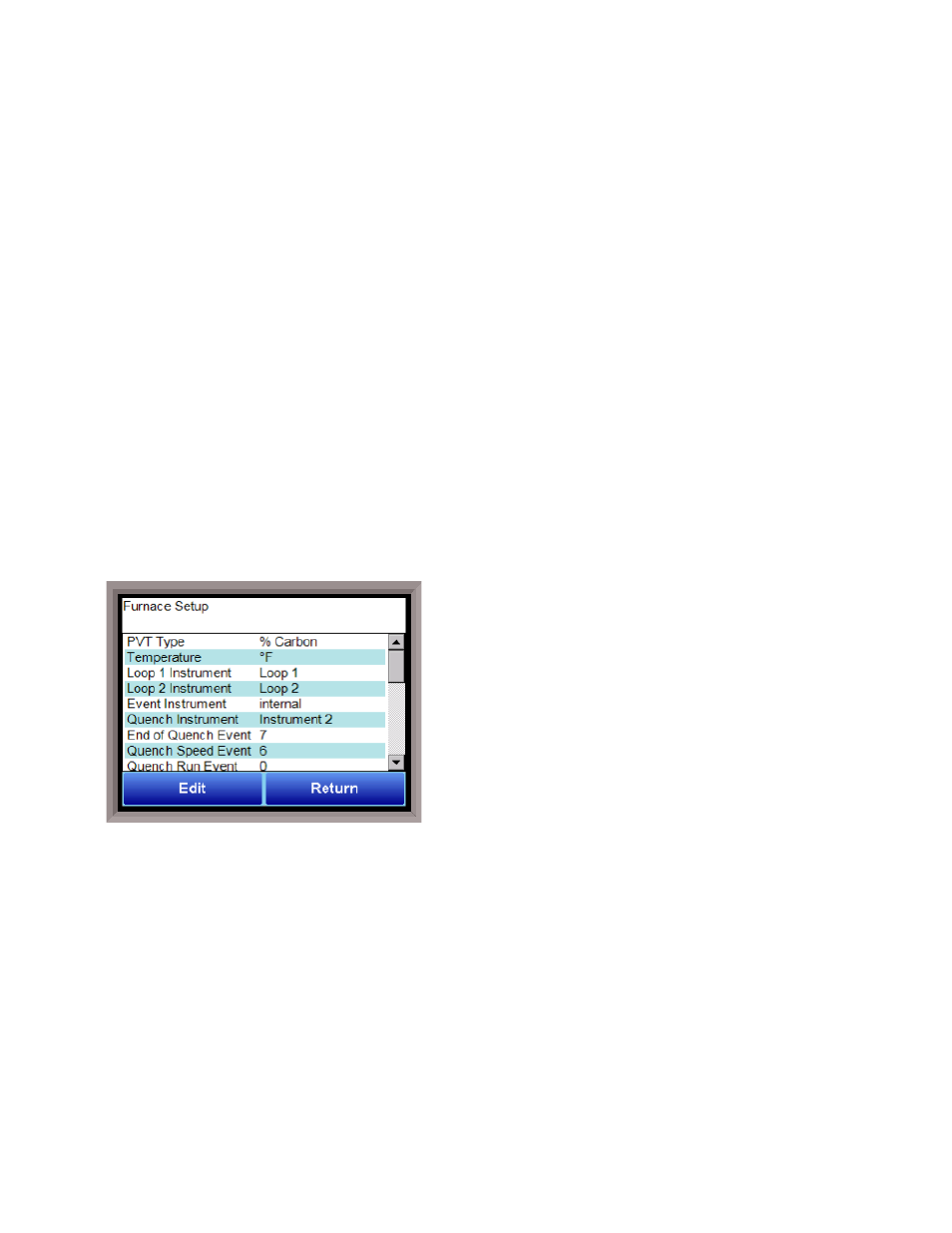
Furnace Setup
The Furnace Setup menu option is an administrative access
only option. Do not make any adjustments on the screen
without first contacting Super Systems, Inc. at (513) 772-
0060.
PVT Type
There are nine PVT choices for the 9205:
%Carbon
Cascade
Dew Point
% Carbon + Redundant TC
Millivolts
Dew Point + Redundant TC
Multiloop
Millivolts + Redundant TC
% Carbon + Dual Temp
%Carbon: Process variable will calculate for carbon potential along with a temperature loop. Loop 1 is
based off of Input 1 (terminals 31, 32 probe sensor millivolts) and Input 2 (terminals 29, 30 probe TC).
These two inputs together constitute loop 1. Loop 2 comes from Input 3 (terminals 27, 28) which is
temperature control.
Cascade: Three loops of temperature control work together in a cascade setting.
Dew Point: Control will be for dew point along with a temperature loop. Loop 1 is based off of Input 1
(terminals 31, 32 probe sensor millivolts) and Input 2 (terminals 29, 30 probe TC). These two inputs
together constitute loop 1. Loop 2 comes from Input 3 (terminals 27, 28) which is temperature control.
%Carbon + Redundant TC: This functions the same way as the %Carbon option with an additional
thermocouple for Loop 3. The two thermocouples are used to control carbon, and the operator can choose
the setting that will be used.