Super Systems 9205 Series User Manual
Page 31
Series 9205 Operations Manual Rev A
30
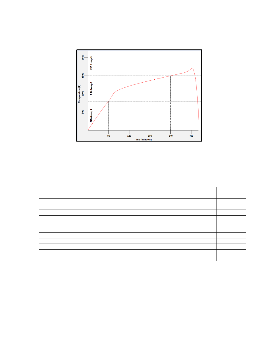
values. These values can be recorded and manually entered as described below. The chart below
demonstrates this feature.
In the example above, proper use of the Tuning Assistant allows the user to find the following optimal PID
settings for the following temperature ranges:
•
0-800F -> PID Group 1 (P = 1.0, I = 2.0, D = 3.0)
•
801-1500F -> PID Group 2 (P = 1.3, I = 2.3, D = 2.3)
•
1501F+ -> PID Group 3 (P = 1.6, I = 2.6, D = 3.6)
The following settings must be made via the touch screen:
Parameter
Value
PID Loop Setup -> Loop 1 -> PID Auto Switch
Yes
PID Loop Setup -> Loop 1 -> Switch Point PID 1-2
800
PID Loop Setup -> Loop 1 -> Switch Point PID 2-3
1500
Alternate PID Setup -> LP1 set 1 -> Prop Band
1.0
Alternate PID Setup -> LP1 set 1 -> Reset
2.0
Alternate PID Setup -> LP1 set 1 -> Rate
3.0
Alternate PID Setup -> LP1 set 2 -> Prop Band
1.3
Alternate PID Setup -> LP1 set 2 -> Reset
2.3
Alternate PID Setup -> LP1 set 2 -> Rate
3.3
Alternate PID Setup -> LP1 set 3 -> Prop Band
1.6
Alternate PID Setup -> LP1 set 3 -> Reset
2.6
Alternate PID Setup -> LP1 set 3 -> Rate
3.6
PID 1 -> 2 Switch Point
This is the PID Switch Point field. This is used in conjunction with the PID Auto Switching feature. See the
PID Auto Switch
section for more information. The range is –300 to 4000.
PID 2 -> 3 Switch Point
This is the PID Switch Point field. This is used in conjunction with the PID Auto Switching feature. See the
PID Auto Switch
section for more information. The range is –300 to 4000.
Setpoint Lower Limit
This is the lower limit of the setpoint. The range is –300 to 9999.