Configure ip addresses, Configure block writes, Df1 configuration – Super Systems 9205 Series User Manual
Page 126: Onfiguration
Series 9205 Operations Manual Rev A
125
Click on the Done button to close the screen and save the changes, or select a new instrument to configure
another instrument.
Configure IP Addresses
This screen will allow the user to set up the IP addresses for the generic instruments, as well as assign a
port number for each instrument. (The IP addresses are independent and can be used for any instrument.)
The first four columns in the grid are for the IP address. The IP address follows the standard format—e.g..,
192.168.1.230. To use this IP for instrument 5, 192 would be entered in the first column, 168 would be
entered for the second column, 1 would be entered for the third column, and 230 would be entered in the
fourth column. The port number would be entered in the fifth column, which also has the “Port” heading.
The IP address columns have a range of 0 – 255, and the Port column has a range of 0 – 32767.
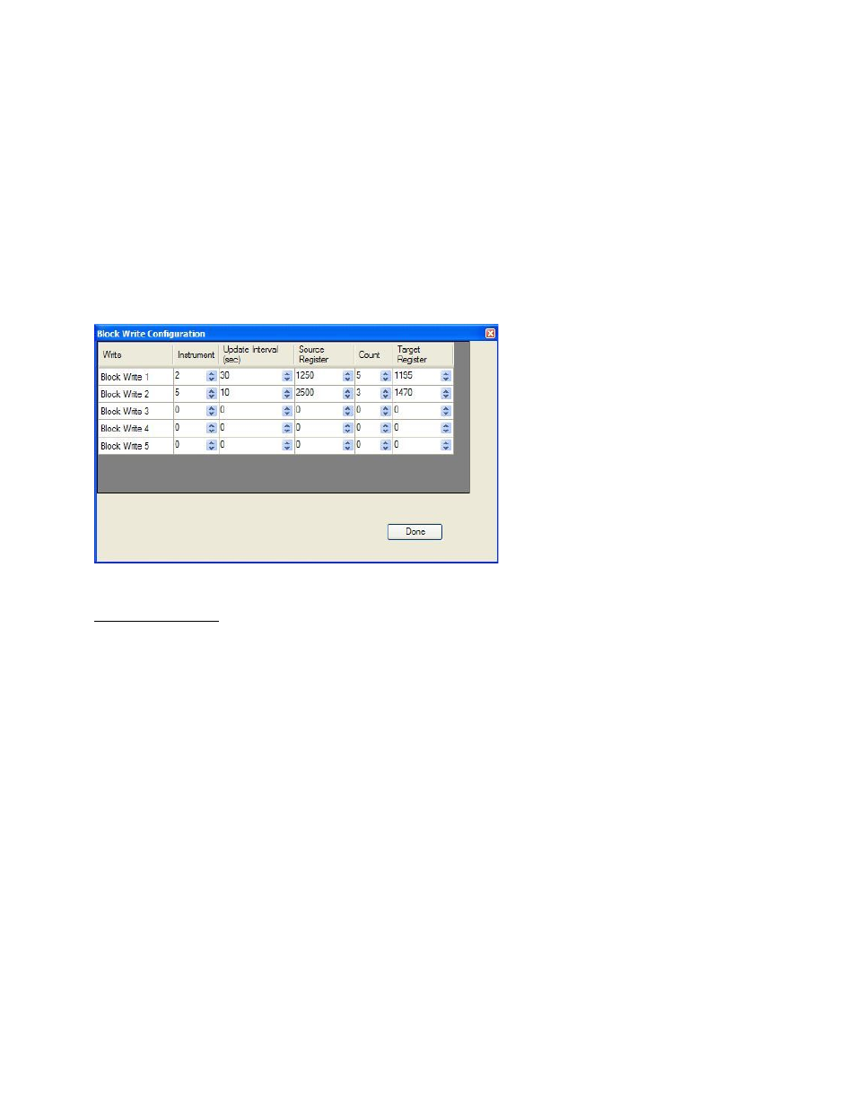
Configure Block Writes
This screen will allow the user to
configure up to five (5) block writes for
the instruments.
The Instrument field is the instrument
to write to. The range is 0 – 32. The
Update Interval field is the update time,
in seconds, to perform the write. The
range is 0 – 300 seconds. The Source
Register field is the 9205 register where
the values will come from. The range is
0 – 32767. The Count field is the
number of successive registers to read.
The range is 0 – 80. The Target
Register field is the slave instrument
start register for the block write. The
range is 0 – 32767.
DF1 Configuration
DF1 Configuration
This option allows the information data from the 9205 to be sent to the PLC DF1 Register map.
My Node
This option will allow the user to select the node. This node must not exist anywhere else on the
computer’s network. The range is 0 to 30000.
PLC node
This option will allow the user to select the PLC node. This must be the node address of a PLC. The range
is 0 to 30000.
PLC read table
This option will allow the user to select the PLC read table. The range is 8 to 255.
PLC write table
This option will allow the user to select the PLC write table. The range is 8 to 255.
PLC intermessage delay
This is the delay time (in milliseconds) between requests sent to the PLC from the 9205 controller. The
request can be for any read or write transaction between the PLC and the 9205. The range is 51 to 5000.