Slave instrument mapping, Atmosphere instruments, Lave – Super Systems 9205 Series User Manual
Page 141: Nstrument, Apping
Series 9205 Operations Manual Rev A
140
Slave Instrument Mapping
The following tables can be used as a reference for retrieving information such as the PV, setpoint, etc from
a slave instrument. The slave instrument information will have a base offset based on the instrument
number that is assigned. The base offset can be determined using the following formula:
Base Offset = (Instrument Number * 100) + 900
For example, the base offset for instrument 1 would be 1000 → (1 * 100) + 900 – and the base offset for
instrument 7 would be 1600 → (7 * 100) +900. The slave instruments will be split into three sections:
Atmosphere Instruments, Temperature Instruments, and Events Instruments. The layout for each
instrument will be the same:
•
Controller – The type of controller the slave instrument is – i.e. AC20, Series 9200, etc.
•
Source Location – The register
in the controller
where the specified value is located.
Note: These
will be added on to the base offset of the instrument (see above section)
. For example, the source
location for %C actual for an AC20 is 11. For instrument 1, the register to find the %C actual would
be 1011 → the base offset for instrument 1 is 1000, plus the source location of 11.
•
Write Register – The register
within the slave instrument
where the value will be written.
•
Read Scale – Any value read in from an instrument will be divided by this number for display
purposes only.
•
Write Scale – Any value written to an instrument will be multiplied by this number for display
purposes only.
•
Description – This will be a brief description of what the value is, i.e. %C actual, Setpoint, etc.
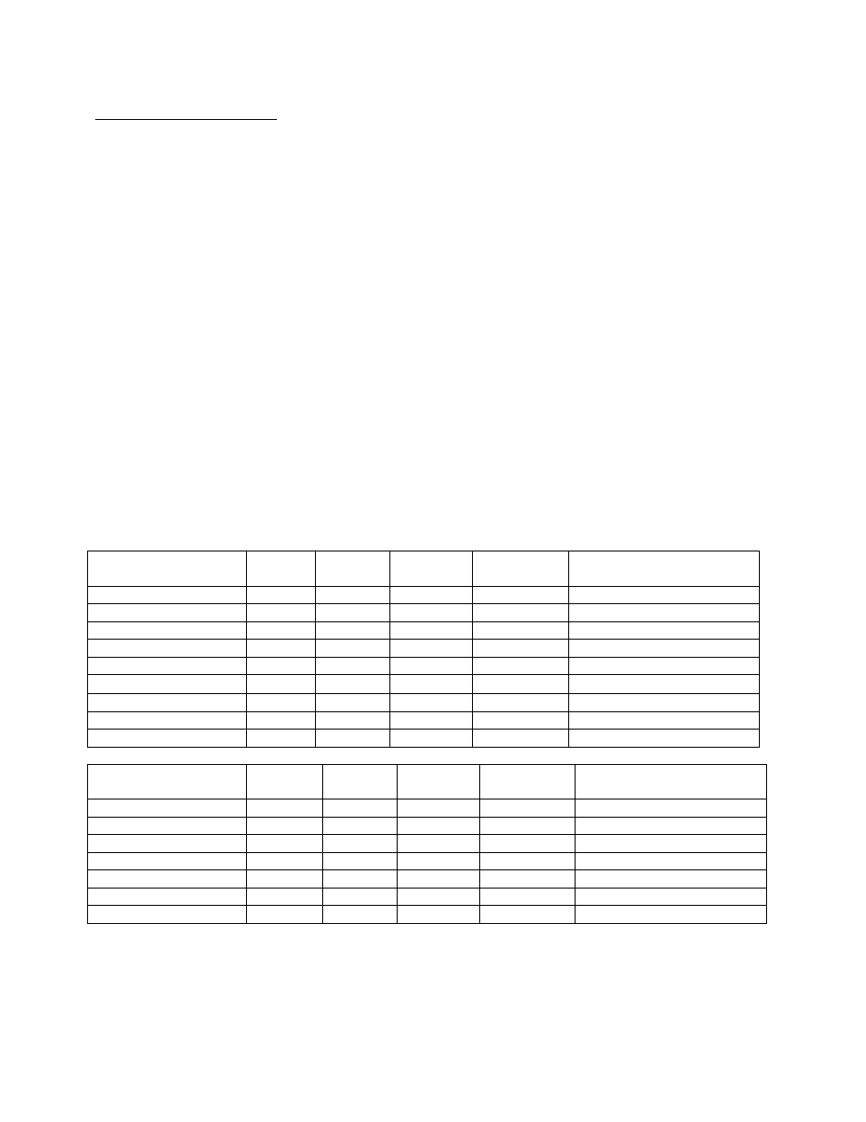
Atmosphere Instruments
Controller
Source
Location
Write
Register
Read
Scale
Write Scale
Description
AC20
11
123
1
1
%C Actual
(Modbus Mode)
29
138
1
1
%C Setpoint
13
125
1
1
Probe Temperature
10
122
1
1
Probe Millivolts
20
130
10
10
%C Percent Output
34
142
1
1
CO Factor or Equivalent
35
143
1
1
H Factor or Equivalent
12
124
1
1
Dew Point
36
144
10
10
O
2
Controller
Source
Location
Write
Register
Read
Scale
Write Scale
Description
Yoko 750
2
2
1
1
%C Actual
(Modbus Mode)
3
100
1
1
%C Setpoint
20
19
1
1
Probe Temperature
10
122
1
1
Probe Millivolts
4
4
10
10
%C Percent Output
0
0
1
1
CO Factor or Equivalent
0
0
1
1
H Factor or Equivalent