Can connections – Basler Electric DGC-2020ES User Manual
Page 107
9469200990 Rev C
99
CAN Connections
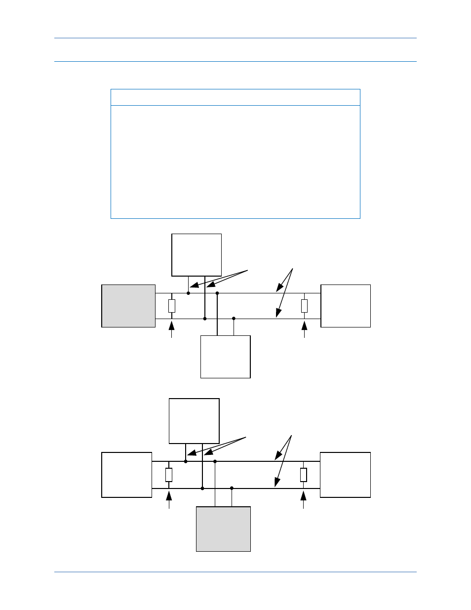
Typical CAN connections are shown in
Note
1.
If the DGC-2020ES is providing one end of the J1939 bus, a
120
Ω, ½ watt terminating resistor should be installed across
terminals 14 (CANL) and 13 (CANH).
2.
If the DGC-2020ES is not providing one end of the J1939 bus, the
stub connecting the DGC-2020ES to the bus should not exceed
914 mm (3 ft) in length.
3.
The maximum bus length, not including stubs, is 40 m (131 ft).
4.
The J1939 drain (shield) should be grounded at one point only. If
grounded elsewhere, do not connect the drain to the DGC-
2020ES.
Figure 53. CAN Interface with DGC-2020ES Providing One End of the Bus
Figure 54. CAN Interface with Other Devices
DGC-2020ES
Other
Devices
P0067-85
Engine
120 ohm
Termination
CAN-H
CAN-L
CEM-2020
(Optional)
120 ohm
Termination
Bus
Stub
DGC-2020ES
Other
Devices
P0067-86
Engine
120 ohm
Termination
CAN-H
CAN-L
CEM-2020
(Optional)
120 ohm
Termination
Bus
Stub
DGC-2020ES
Typical Connections