Basler Electric DGC-2020ES User Manual
Page 150
Advertising
142
9469200990 Rev C
Figure 73. Example 2 – AND Gate Connections
Example 3 - Multiple Logic Connections
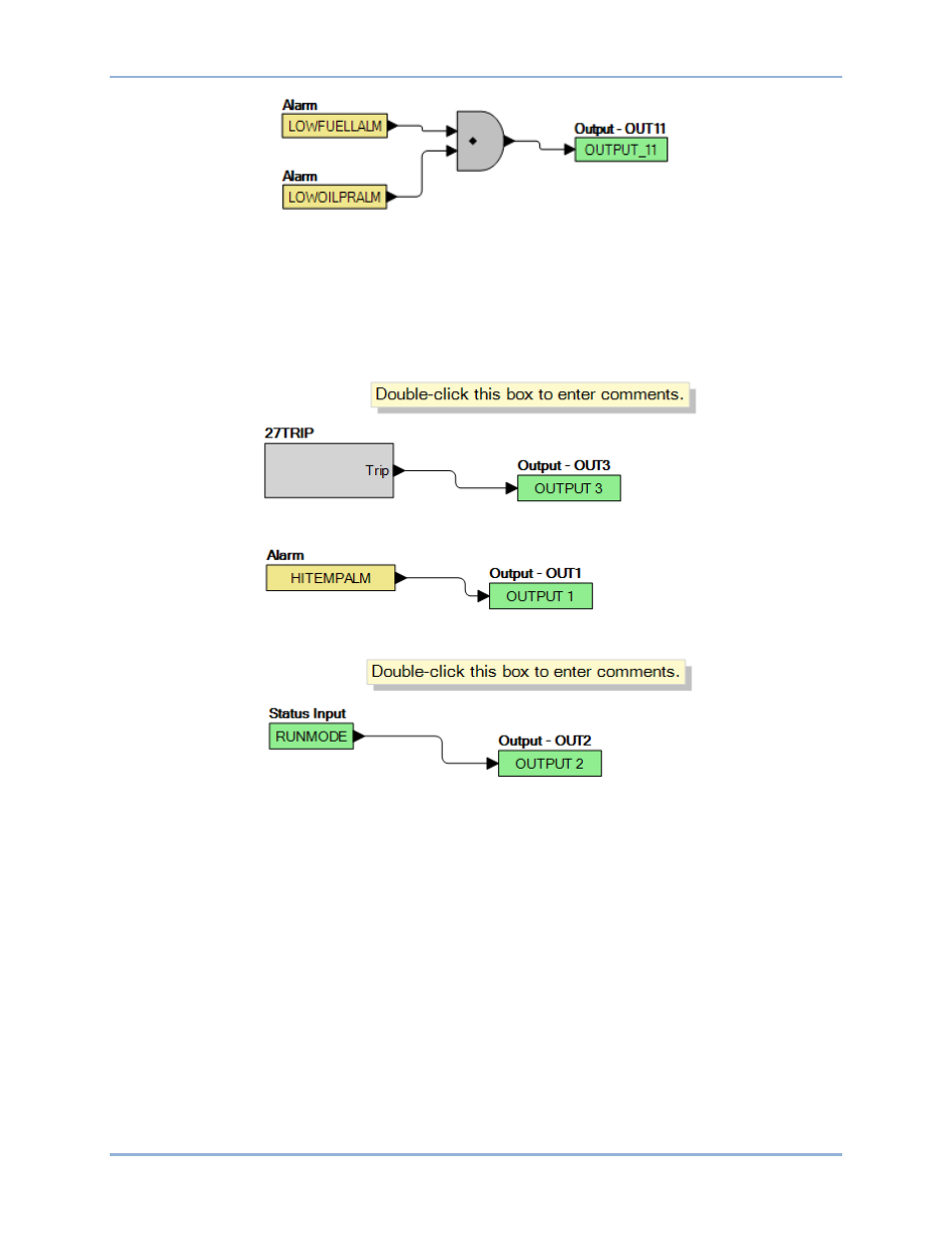
In this example, there are two comment boxes, which may be placed on the logic diagram. Double-click a
comment box to modify the inside text. Output 3 becomes true when the 27TRIP is true. Output 1
becomes true when the High Coolant Temp is true. Output 2 becomes true when the DGC-2020ES is in
RUN mode (RUN Mode true). Refer to Figure 74.
Figure 74. Example 3 – Multiple Logic Connections
BESTlogic
™Plus
DGC-2020ES
Advertising