Casella CEL CEL-281 User Manual
Page 126
Advertising
The connector is keyed so that the plug can be inserted only the
correct way.
7.
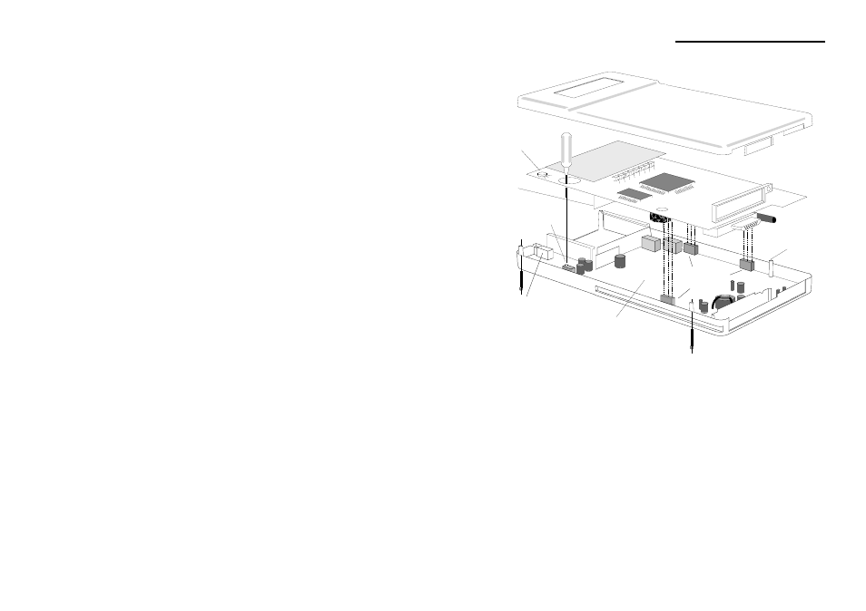
Carefully replace the upper circuit board.
Locate the three 3-pin connectors, and make sure the contact
strip comes inside the battery compartment.
8.
Without replacing the front cover at this time, insert a fully
loaded battery holder into the battery compartment.
9.
Either hold the battery pack in place by hand to ensure a good
electrical contact, or slip an elastic band round the instrument.
Figure 23: Replacing the microphone
Spacer
910039
Adjust This
Potentiometer
DO NOT
Adjust This
Potentiometer
Contact
Front Cover
Upper Board
Lower Board
Rear Cover
Strip
Controls Cover
Insert
Three x 3-pin
Connectors
Microphone
Socket
Technical Information
CEL-281 Operator's Handbook - Page 117
Advertising