How it works – Casella CEL CEL-281 User Manual
Page 39
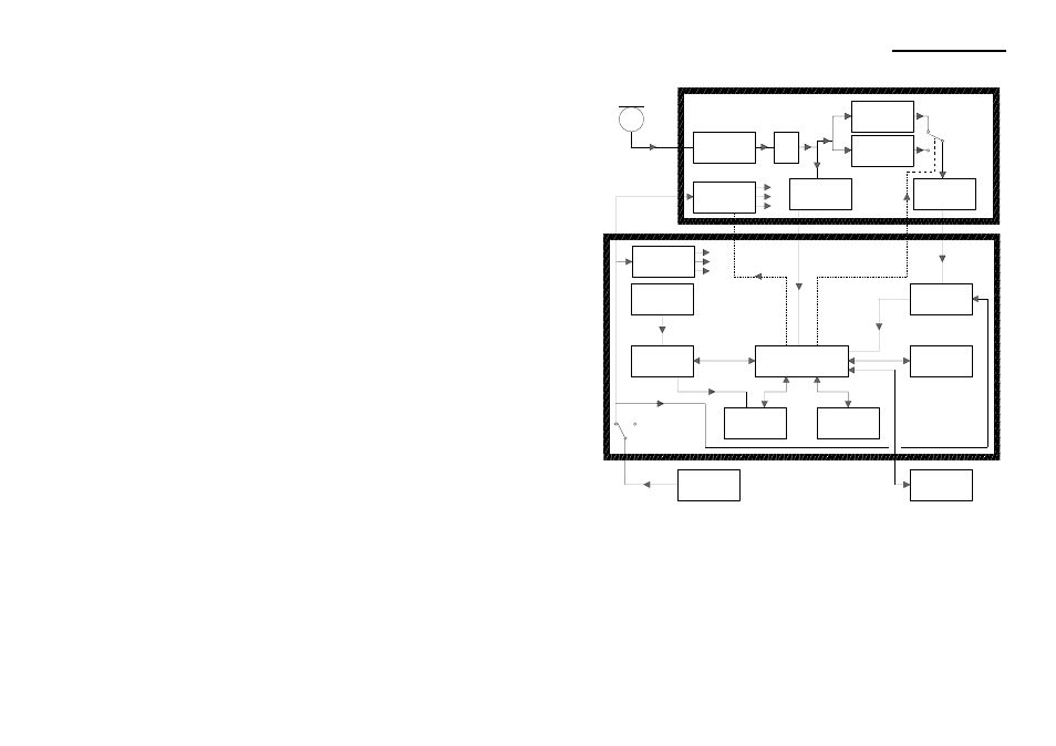
Signals from the microphone are amplified and passed through an A- or
C-weighting circuit, as selected by the operator. Both weightings comply
with the requirements of IEC 651. The output from the preamplifier is
also passed to an overload detector connected directly to the microproc-
essor.
The output from the frequency weighting circuit in use passes to a wide
range RMS detector with a very rapid response time which also converts
Preamplifier
RMS & Log
Conversion
Overload
Detector
Analog Sect.
Power Sup.
Digital Sect.
Power Sup.
Analog to
Digital Conv.
EPROM
RAM
Clock
Microprocessor
Battery
Pack
Memory &
Clock
Back-up Bat.
Microphone
A/C Select
On/Off Control
Analog Section
Digital Section
900164
Connector
15-line
Display
A-weighting
C-weighting
Latching
Push Button
Pot.
Trim
Figure 6: Block diagram of the CEL-281
CEL-281 Operator's Handbook - Page 31
How It Works