Configuration procedure, N in, Figure 31 – H3C Technologies H3C S12500 Series Switches User Manual
Page 115
102
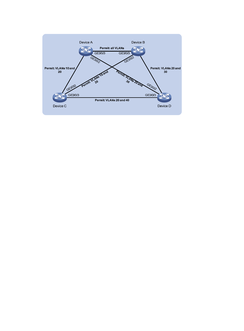
Figure 31 Network diagram
Configuration procedure
1.
Configure VLANs and VLAN member ports: (Details not shown.)
{
Create VLAN 10, VLAN 20, and VLAN 30 on Device A and Device B.
{
Create VLAN 10, VLAN 20, and VLAN 40 on Device C.
{
Create VLAN 20, VLAN 30, and VLAN 40 on Device D.
{
Configure the ports on these devices as trunk ports and assign them to related VLANs.
2.
Configure Device A:
# Set the spanning tree mode to PVST.
<DeviceA> system-view
[DeviceA] stp mode pvst
# Specify the device as the root bridge of VLAN 10 and VLAN 20.
[DeviceA] stp vlan 10 20 root primary
# Enable the spanning tree feature globally, and enable the spanning tree feature for VLANs 10,
20, and 30.
[DeviceA] stp enable
[DeviceA] stp vlan 10 20 30 enable
3.
Configure Device B:
# Set the spanning tree mode to PVST.
<DeviceB> system-view
[DeviceB] stp mode pvst
# Specify the device as the root bridge of VLAN 30.
[DeviceB] stp vlan 30 root primary
# Enable the spanning tree feature globally, and enable the spanning tree feature for VLANs 10,
20, and 30.
[DeviceB] stp enable
[DeviceB] stp vlan 10 20 30 enable
4.
Configure Device C:
# Set the spanning tree mode to PVST.
G
E
3
/0
/1
G
E
3
/0
/1
G
E
3
/0
/1
G
E
3
/0
/1