Network requirements, Configuration considerations and guidelines – H3C Technologies H3C S12500 Series Switches User Manual
Page 214
201
Ambiguous QinQ termination configuration example (lite
solution)
In this example, customer network VLANs (CVLANs), also called inner VLANs, refer to the VLANs that
a customer uses on the private network. Service provider network VLANs (SVLANs), also called outer
VLANs, refer to the VLANs that a service provider uses to carry VLAN tagged traffic for customers.
Network requirements
As shown in
, Layer 3 Switch C is a core network device of a service provider. It connects to
Layer 2 Switch A and Layer 2 Switch B through access ports GigabitEthernet 3/0/1 and GigabitEthernet
3/0/2, respectively.
Layer 3 Switch C also connects to a server group through Layer 2 Switch D. Layer 2 Switch D can process
only single-tagged VLAN packets.
On customer networks A and B, Host A1 and Host A2 are assigned to CVLAN 11, Host B1 and Host B2
are assigned to CVLAN 12, and Host C2 and Host C2 are assigned to CVLAN 13.
Enable QinQ on GigabitEthernet 3/0/1 and GigabitEthernet 3/0/2 of Layer 3 Switch C to add SVLAN
100 and SVLAN 200 to packets carrying CVLANs 11 through 13 as the outermost VLAN tag, respectively,
so the packets are isolated at Layer 2.
Configure QinQ termination on the VLAN interfaces of Layer 3 Switch C to enable all hosts on the
customer networks to communicate with the server group and to enable hosts on customer network A to
communicate with hosts on customer network B at Layer 3.
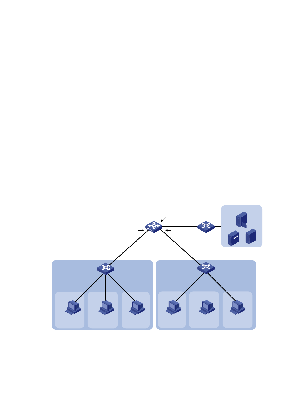
Figure 74 Network diagram
Configuration considerations and guidelines
Make sure the number of the current VLAN interface is excluded from the inner VLAN ID range. For
example, when you configure the second-dot1q { vlan-list | any } command on VLAN-interface 100,
make sure vlan-list does not include 100 and do not use the any keyword.
L3 Switch C
Host A2
2.1.1.1/24
Host B2
2.1.1.2/24
Host C2
2.1.1.3/24
VLAN 12
VLAN 13
L2 Switch B
VLAN 11
L2 Switch A
Host A1
1.1.1.1/24
Host B1
1.1.1.2/24
Host C1
1.1.1.3/24
VLAN 11
VLAN 12
VLAN 13
Server group
L2 Switch D
GE1/0/7
Vlan-int100
1.1.1.11/24
Vlan-int200
2.1.1.11/24
GE3/0/1
VLAN 100
QinQ enabled
GE3/0/2
VLAN 200
QinQ enabled
GE3/0/3
Vlan-int300
3.1.1.11/24
GE1/0/1
GE1/0/2
GE1/0/3
Customer
network A
Customer
network B