Configuring bpdu tunneling, Overview, Background – H3C Technologies H3C S12500 Series Switches User Manual
Page 178
165
Configuring BPDU tunneling
Overview
As a Layer 2 tunneling technology, Bridge Protocol Data Unit (BPDU) tunneling enables Layer 2 protocol
packets from geographically dispersed customer networks to be transparently transmitted over specific
tunnels across a service provider network.
Background
Dedicated lines are used in a service provider network to build user-specific Layer 2 networks. As a result,
a user network is broken down into parts located at different sides of the service provider network. As
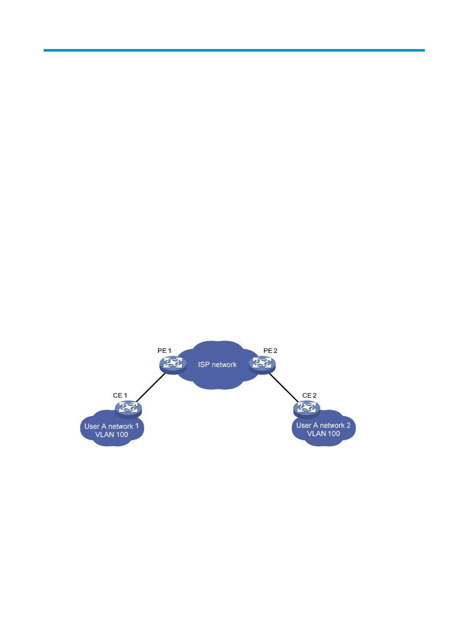
shown in
, User A has two devices (CE 1 and CE 2) and both devices belong to VLAN 100.
User A’s network is divided into network 1 and network 2, which are connected by the service provider
network. When a Layer 2 protocol (for example, STP) runs on both network 1 and network 2, the Layer
2 protocol packets must be transmitted over the service provider network to implement Layer 2 protocol
calculation (for example, spanning tree calculation). When receiving a Layer 2 protocol packet, the PEs
cannot determine whether the packet is from the user network or the service provider network, and must
deliver the packet to the CPU for processing. In this case, the Layer 2 protocol calculation in User A’s
network is mixed with that in the service provider network, and the user network cannot implement
independent Layer 2 protocol calculation.
Figure 56 BPDU tunneling application scenario
With BPDU tunneling, Layer 2 protocol packets from customer networks can be transparently transmitted
over the service provider network in the following workflow:
1.
After receiving a Layer 2 protocol packet from CE 1, PE 1 encapsulates the packet, replaces its
destination MAC address with a specific multicast MAC address, and forwards the packet to the
service provider network.
2.
The encapsulated Layer 2 protocol packet (called bridge protocol data unit, BPDU) is forwarded
to PE 2 at the other end of the service provider network, which de-encapsulates the packet, restores
the original destination MAC address of the packet, and then sends the packet to CE 2.