Network requirements, Configuring pe 1 – H3C Technologies H3C S12500 Series Switches User Manual
Page 175
162
# Assign network-side port GigabitEthernet 4/0/2 to the CVLAN and SVLAN.
[SwitchA] interface ethernet gigabitethernet 4/0/2
[SwitchA-GigabitEthernet4/0/2] port link-type trunk
[SwitchA-GigabitEthernet4/0/2] port trunk permit vlan 10 100
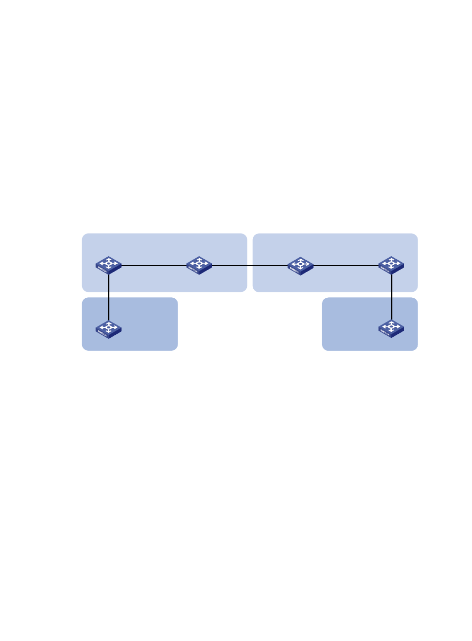
One-to-two and two-to-two VLAN mapping configuration
example
Network requirements
As shown in
, Site 1 and Site 2, two remote users in VPN A, are in VLAN 10. SP 1 assigns
VLAN 100 to VPN A, and SP 2 assigns VLAN 200 to VPN A.
Configure one-to-two and two-to-two VLAN mappings to enable the two sites to communicate across the
two SP networks.
Figure 55 Network diagram
Configuring PE 1
# Configure uplink policy test to add outer VLAN tag 100 to VLAN 10 tagged traffic.
<PE1> system-view
[PE1] traffic classifier test
[PE1-classifier-test] if-match service-vlan-id 10
[PE1-classifier-test] quit
[PE1] traffic behavior test
[PE1-behavior-test] nest top-most vlan-id 100
[PE1-behavior-test] quit
[PE1] qos policy test
[PE1-qospolicy-test] classifier test behavior test
[PE1-qospolicy-test] quit
# Set customer-side port GigabitEthernet 4/0/1 as a hybrid port, and assign it to VLAN 100 as an
untagged member, so the port forwards VLAN 100 traffic with the VLAN tag removed. Apply uplink
policy test to the incoming traffic.
[PE1] interface gigabitethernet 4/0/1
[PE1-GigabitEthernet4/0/1] port link-type hybrid
[PE1-GigabitEthernet4/0/1] port hybrid vlan 100 untagged
[PE1-GigabitEthernet4/0/1] qos apply policy test inbound
PE 1
VPN A
Site 1
SP 1
CE a1
VPN A
Site 2
SP 2
CE a2
PE 2
PE 3
PE 4
VLAN 10
VLAN 10
GE4/0/1
VLAN 10, 100
GE4/0/2
GE4/0/1
VLAN 10, 100
GE4/0/2
VLAN 10, 100
GE4/0/1
VLAN 10, 200
GE4/0/2
VLAN 10, 200
GE4/0/2
GE4/0/1
VLAN 10, 200