Configuration procedure – H3C Technologies H3C S12500 Series Switches User Manual
Page 139
126
•
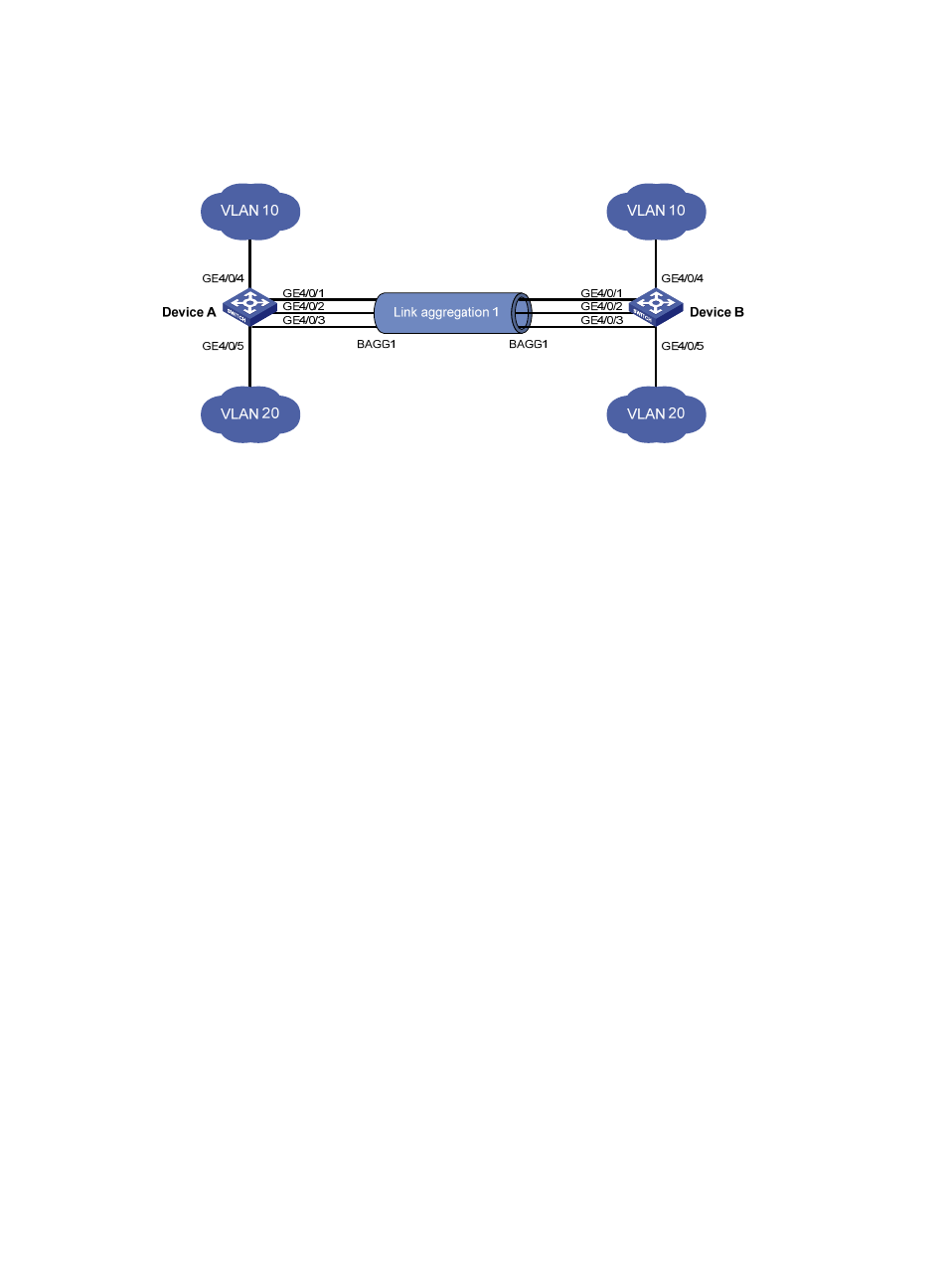
Enable traffic to be load-shared across aggregation group member ports based on source and
destination MAC addresses.
Figure 37 Network diagram
Configuration procedure
1.
Configure Device A:
# Create VLAN 10, and assign the port GigabitEthernet 4/0/4 to VLAN 10.
<DeviceA> system-view
[DeviceA] vlan 10
[DeviceA-vlan10] port gigabitethernet 4/0/4
[DeviceA-vlan10] quit
# Create VLAN 20, and assign the port GigabitEthernet 4/0/5 to VLAN 20.
[DeviceA] vlan 20
[DeviceA-vlan20] port gigabitethernet 4/0/5
[DeviceA-vlan20] quit
# Create Layer 2 aggregate interface Bridge-Aggregation 1, and configure the link aggregation
mode as dynamic.
[DeviceA] interface bridge-aggregation 1
[DeviceA-Bridge-Aggregation1] link-aggregation mode dynamic
# Assign ports GigabitEthernet 4/0/1 through GigabitEthernet 4/0/3 to link aggregation group
1.
[DeviceA] interface gigabitethernet 4/0/1
[DeviceA-GigabitEthernet4/0/1] port link-aggregation group 1
[DeviceA-GigabitEthernet4/0/1] quit
[DeviceA] interface gigabitethernet 4/0/2
[DeviceA-GigabitEthernet4/0/2] port link-aggregation group 1
[DeviceA-GigabitEthernet4/0/2] quit
[DeviceA] interface gigabitethernet 4/0/3
[DeviceA-GigabitEthernet4/0/3] port link-aggregation group 1
[DeviceA-GigabitEthernet4/0/3] quit
# Configure Layer 2 aggregate interface Bridge-Aggregation 1 as a trunk port and assign it to
VLANs 10 and 20.
[DeviceA] interface bridge-aggregation 1
[DeviceA-Bridge-Aggregation1] port link-type trunk
[DeviceA-Bridge-Aggregation1] port trunk permit vlan 10 20