Layer 2 static aggregation configuration example, Network requirements, Configuration procedure – H3C Technologies H3C S12500 Series Switches User Manual
Page 137
124
Layer 2 static aggregation configuration example
Network requirements
As shown in
:
•
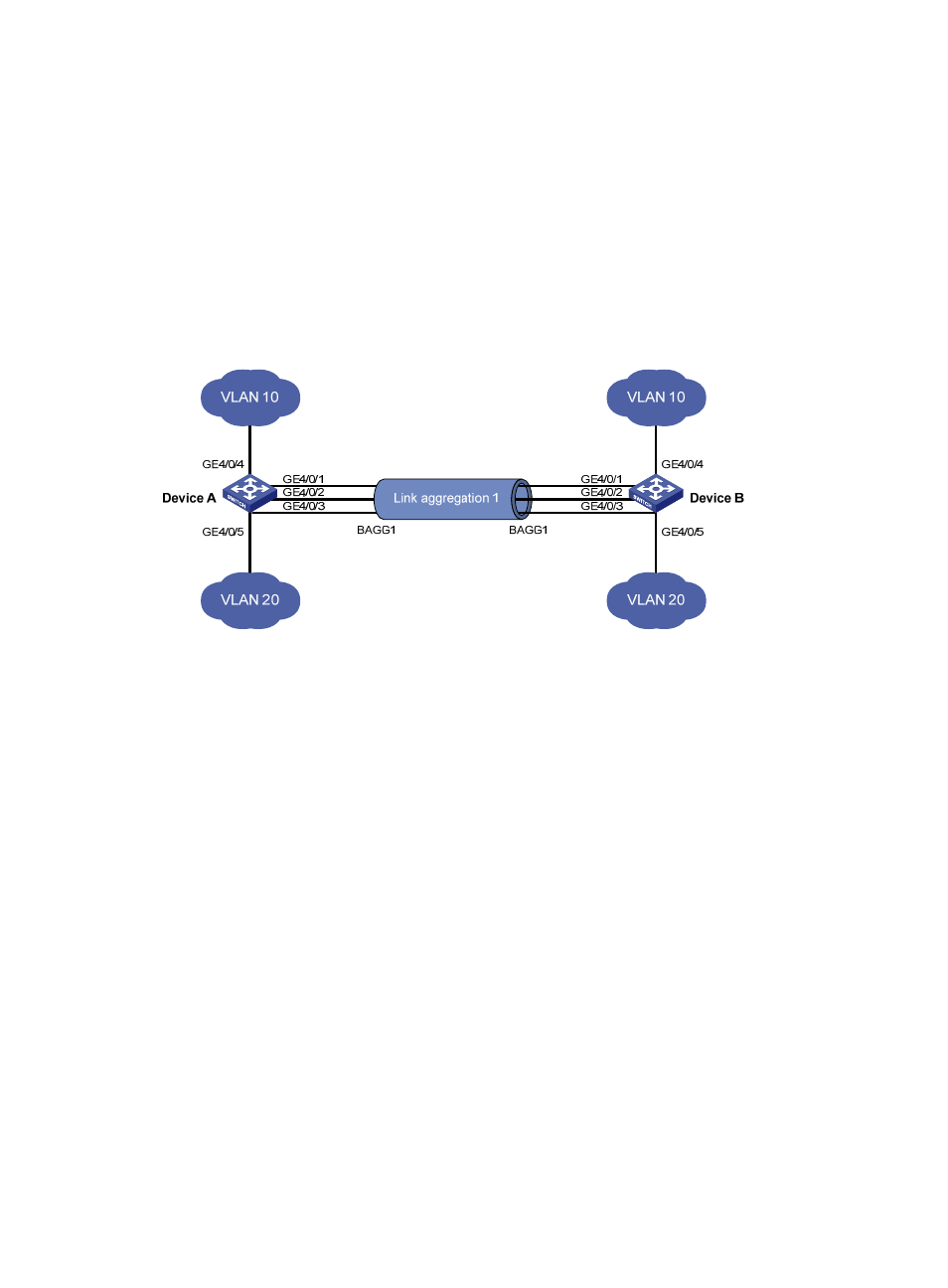
Configure a Layer 2 static link aggregation group on both Device A and Device B, and enable
VLAN 10 at one end of the aggregate link to communicate with VLAN 10 at the other end, and
VLAN 20 at one end to communicate with VLAN 20 at the other end.
•
Enable traffic to be load-shared across aggregation group member ports based on source and
destination MAC addresses.
Figure 36 Network diagram
Configuration procedure
1.
Configure Device A:
# Create VLAN 10, and assign port GigabitEthernet 4/0/4 to VLAN 10.
<DeviceA> system-view
[DeviceA] vlan 10
[DeviceA-vlan10] port gigabitethernet 4/0/4
[DeviceA-vlan10] quit
# Create VLAN 20, and assign port GigabitEthernet 4/0/5 to VLAN 20.
[DeviceA] vlan 20
[DeviceA-vlan20] port gigabitethernet 4/0/5
[DeviceA-vlan20] quit
# Create Layer 2 aggregate interface Bridge-Aggregation 1.
[DeviceA] interface bridge-aggregation 1
[DeviceA-Bridge-Aggregation1] quit
# Assign ports GigabitEthernet 4/0/1 through GigabitEthernet 4/0/3 to link aggregation group
1.
[DeviceA] interface gigabitethernet 4/0/1
[DeviceA-GigabitEthernet4/0/1] port link-aggregation group 1
[DeviceA-GigabitEthernet4/0/1] quit
[DeviceA] interface gigabitethernet 4/0/2
[DeviceA-GigabitEthernet4/0/2] port link-aggregation group 1
[DeviceA-GigabitEthernet4/0/2] quit