Mvrp configuration examples, Network requirements, Configuration procedure – H3C Technologies H3C S12500 Series Switches User Manual
Page 255
242
Task Command
Remarks
Clear the MVRP statistics of
the specified ports.
reset mvrp statistics [ interface interface-list ] Available in user view.
MVRP configuration examples
Configuration example for MVRP in normal registration mode
Network requirements
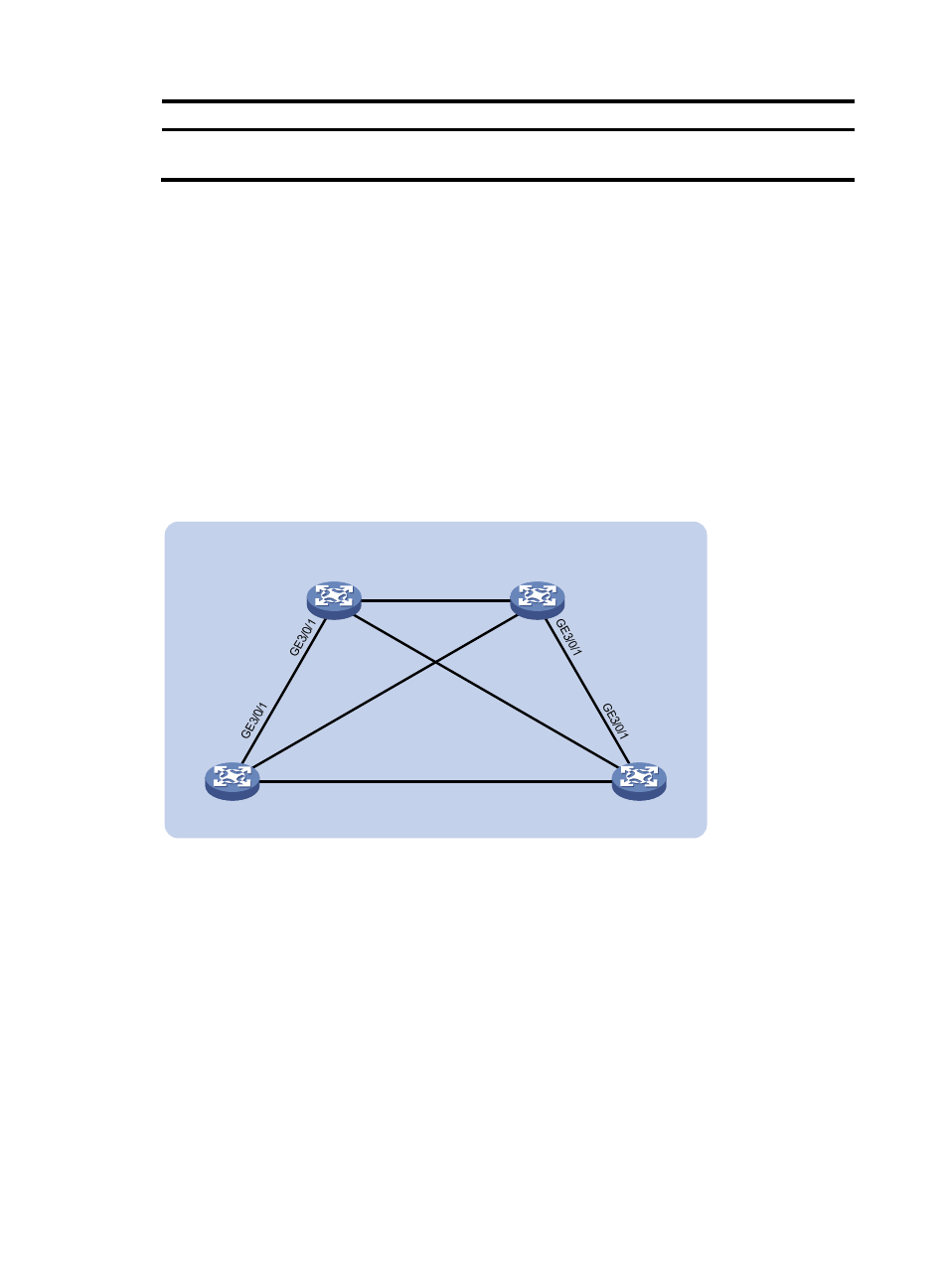
As shown in
, configure MSTP, map VLAN 10 to MSTI 1, map VLAN 20 MST 2, and map the
other VLANs to MSTI 0.
Configure MVRP and set the MVRP registration mode to normal, so that Device A, Device B, Device C,
and Device D can register and deregister dynamic and static VLANs and keep identical VLAN
configuration for each MSTI.
Figure 87 Network diagram
Configuration procedure
1.
Configure Device A:
# Enter MST region view.
<DeviceA> system-view
[DeviceA] stp region-configuration
# Configure the MST region name, VLAN-to-instance mappings, and revision level.
[DeviceA-mst-region] region-name example
[DeviceA-mst-region] instance 1 vlan 10
[DeviceA-mst-region] instance 2 vlan 20
[DeviceA-mst-region] revision-level 0
# Manually activate the MST region configuration.
[DeviceA-mst-region] active region-configuration
[DeviceA-mst-region] quit
Permit: all VLAN
Per
mit:
VL
AN
40
Pe
rm
it:
al
l V
LA
N
Permit: VLAN 30, 40
Permit: VLAN 20, 40
Permit: all VLAN
Device A
Device B
Device C
Device D
GE3/0/3
GE
3/0
/2
GE3/0/3
GE
3/0
/2
GE3/0/3
GE3/0/3
GE
3/0
/2
GE
3/0
/2
MST region