Network requirements, Configuration procedure – H3C Technologies H3C S12500 Series Switches User Manual
Page 148

135
Port-isolate group information:
Uplink port support: NO
Group ID: 2
Group members:
GigabitEthernet4/0/2 GigabitEthernet4/0/3 GigabitEthernet4/0/4
Port isolation with community VLAN configuration example
Network requirements
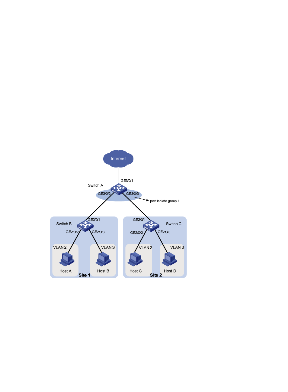
As shown in
, Switch A accesses the Internet through GigabitEthernet 3/0/1. The company
branches Site 1 and Site 2 transfer service traffic in VLAN 2 and VLAN 3, and are connected to Switch
A through Switch B and Switch C, respectively.
Configure port isolation and community VLANs, so the switches allow the company hosts to access the
Internet, enable Host B and Host D to exchange video conferencing traffic in VLAN 3, and isolate other
Layer 2 traffic between Switch B and Switch C.
Figure 42 Network diagram
Configuration procedure
1.
Configuring Switch A:
# Create VLAN 2 and VLAN 3, and assign trunk ports GigabitEthernet 3/0/2 and
GigabitEthernet 3/0/3 to the VLANs.
<SwitchA> system-view
[SwitchA] vlan 2 to 3
[SwitchA] interface GigabitEthernet 3/0/2
[SwitchA-GigabitEthernet3/0/2] port link-type trunk
[SwitchA-GigabitEthernet3/0/2] port trunk permit vlan 2 3
[SwitchA-GigabitEthernet3/0/2] quit