Bpdu tunneling implementation – H3C Technologies H3C S12500 Series Switches User Manual
Page 179
166
BPDU tunneling implementation
To avoid loops in your network, you can enable STP on your switch. When the topology changes at one
side of the customer network, the devices at this side of the customer network send BPDUs to devices on
the other side of the customer network to ensure consistent spanning tree calculation in the entire
customer network. However, because BPDUs are Layer 2 multicast frames, all STP-enabled devices, both
in the customer network and in the service provider network, can receive and process these BPDUs. In this
case, neither the service provider network nor the customer network can correctly calculate its
independent spanning tree.
To allow each network to calculate an independent spanning tree with STP, BPDU tunneling was
introduced.
BPDU tunneling delivers the following benefits:
•
BPDUs can be transparently transmitted. BPDUs of one customer network can be broadcast in a
specific VLAN across the service provider network, allowing that customer’s geographically
dispersed networks to implement consistent spanning tree calculation across the service provider
network.
•
BPDUs of different customer networks can be confined within different VLANs for transmission on
the service provider network, so each customer network can perform independent spanning tree
calculation.
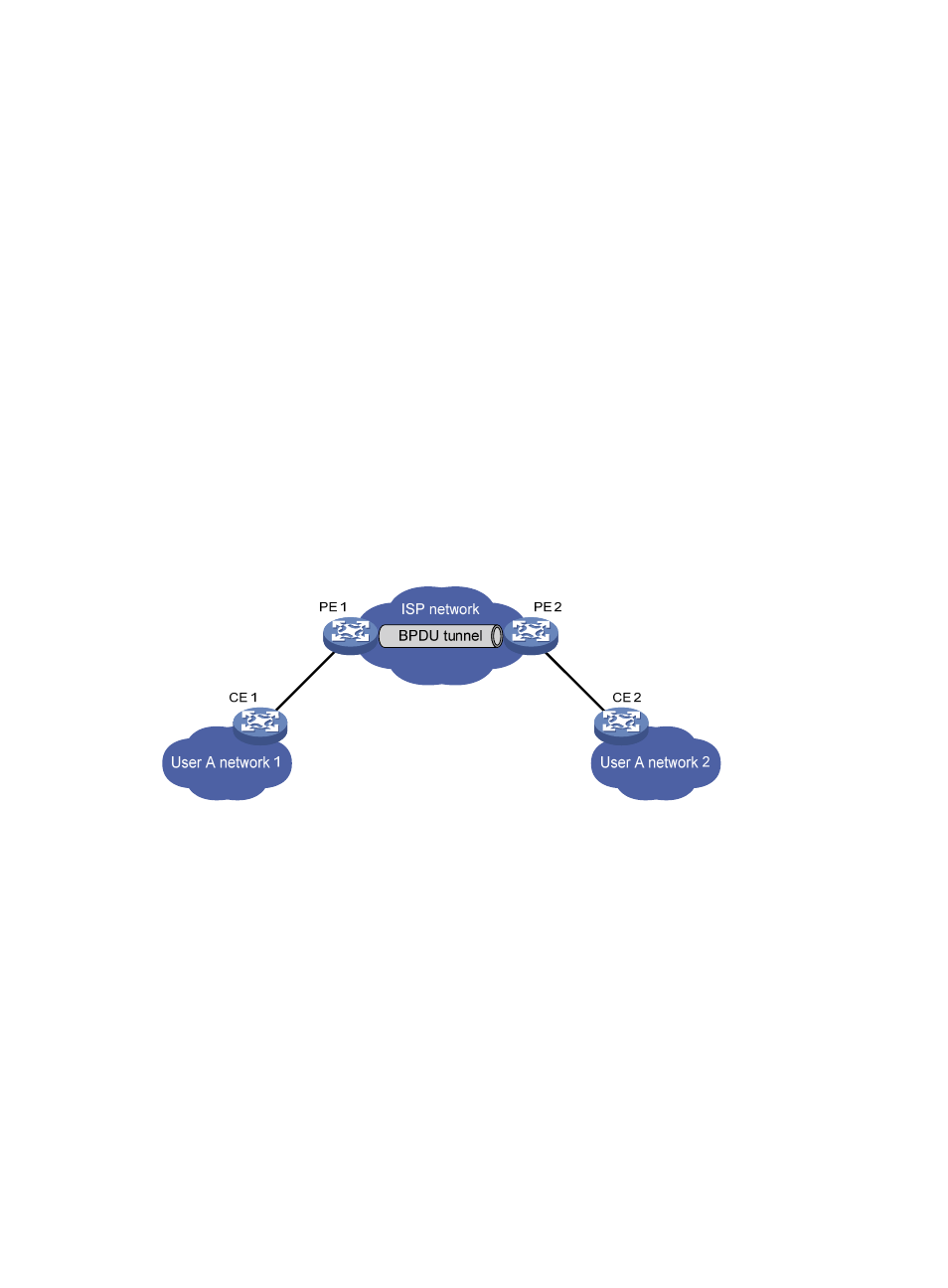
Figure 57 BPDU tunneling implementation
The upper section of
represents the service provider network (ISP network), and the lower
section, including User A network 1 and User A network 2, represents customer networks. Enabling
BPDU tunneling on edge devices (PE 1 and PE 2) in the service provider network allows BPDUs of User
A network 1 and User A network 2 to be transparently transmitted through the service provider network,
thus ensuring consistent spanning tree calculation throughout User A network, without affecting the
spanning tree calculation of the service provider network.
Assume a BPDU is sent from User A network 1 to User A network 2:
1.
At the ingress of the service provider network, PE 1 changes the destination MAC address of the
BPDU from 0x0180-C200-0000 to a special multicast MAC address, 0x010F-E200-0003 (the
default multicast MAC address) for example. In the service provider network, the modified BPDU
is forwarded as a data packet in the VLAN assigned to User A.
2.
At the egress of the service provider network, PE 2 recognizes the BPDU with the destination MAC
address 0x010F-E200-0003, restores its original destination MAC address 0x0180-C200-0000,
and then sends the BPDU to CE 2.