Configuration procedure – H3C Technologies H3C S12500 Series Switches User Manual
Page 212
199
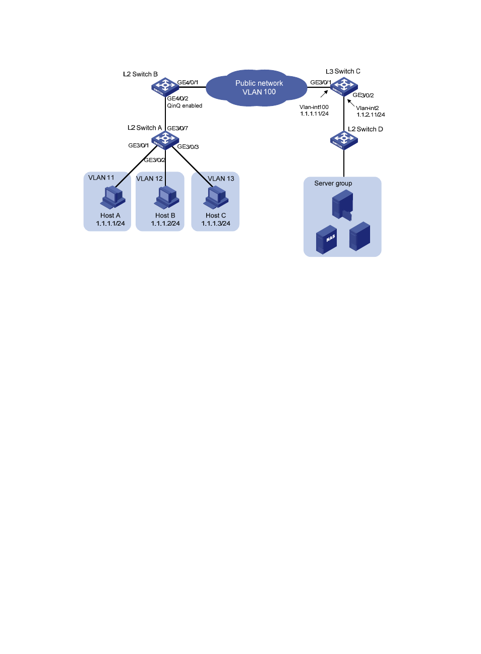
Figure 73 Network diagram
Configuration procedure
1.
Configure Host A, Host B, and Host C:
{
Configure the IP addresses of Host A, Host B, and Host C as 1.1.1.1/24, 1.1.1.2/24, and
1.1.1.3/24, respectively.
{
Configure the gateway address as 1.1.1.11/24 for the hosts.
2.
Configure Layer 2 Switch A:
# Assign GigabitEthernet 3/0/1 to VLAN 11.
<L2_SwitchA> system-view
[L2_SwitchA] vlan 11
[L2_SwitchA-vlan11] port GigabitEthernet 3/0/1
[L2_SwitchA-vlan11] quit
# Assign GigabitEthernet 3/0/2 to VLAN 12.
[L2_SwitchA] vlan 12
[L2_SwitchA-vlan12] port GigabitEthernet 3/0/2
[L2_SwitchA-vlan12] quit
# Assign GigabitEthernet 3/0/3 to VLAN 13.
[L2_SwitchA] vlan 13
[L2_SwitchA-vlan13] port GigabitEthernet 3/0/3
[L2_SwitchA-vlan13] quit
# Configure GigabitEthernet 3/0/7 as a hybrid port and assign the port to VLANs 11 through 13
as a tagged member.
[L2_SwitchA] interface GigabitEthernet 3/0/7
[L2_SwitchA-GigabitEthernet3/0/7] port link-type hybrid
[L2_SwitchA-GigabitEthernet3/0/7] port hybrid vlan 11 to 13 tagged
3.
Configure Layer 2 Switch B:
# Configure GigabitEthernet 4/0/2 as a trunk port, and assign the port to VLAN 100.