Network diagram, Configuration procedure – H3C Technologies H3C S7500E Series Switches User Manual
Page 104
4-20
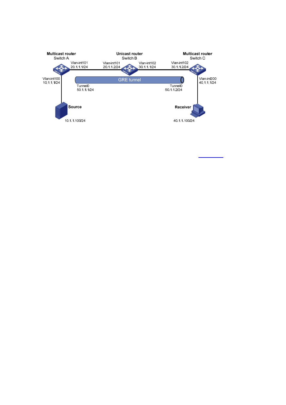
Network diagram
Figure 4-7 Network diagram for configuring multicast forwarding over a GRE tunnel
Configuration procedure
1) Configure
IP
addresses
Configure the IP address and mask for each interface as per
. The detailed
configuration steps are omitted here.
2) Configure a GRE tunnel
# Create Tunnel 0 on Switch A and configure the IP address and mask for the interface.
<SwitchA> system-view
[SwitchA] interface tunnel 0
[SwitchA-Tunnel0] ip address 50.1.1.1 24
# Configure Tunnel 0 to work in the GRE tunnel mode and specify the source and destination
addresses of the interface.
[SwitchA-Tunnel0] tunnel-protocol gre
[SwitchA-Tunnel0] source 20.1.1.1
[SwitchA-Tunnel0] destination 30.1.1.2
[SwitchA-Tunnel0] quit
# Create Tunnel 0 on Switch C and configure the IP address and mask for the interface.
<SwitchC> system-view
[SwitchC] interface tunnel 0
[SwitchC-Tunnel0] ip address 50.1.1.2 24
# Configure Tunnel to operate in the GRE tunnel mode and configure the source and
destination addresses of the interface.
[SwitchC-Tunnel0] tunnel-protocol gre
[SwitchC-Tunnel0] source 30.1.1.2
[SwitchC-Tunnel0] destination 20.1.1.1
[SwitchC-Tunnel0] quit
3) Configure
OSPF.
# Configure OSPF on Switch A.
[SwitchA] ospf 1
[SwitchA-ospf-1] area 0
[SwitchA-ospf-1-area-0.0.0.0] network 10.1.1.0 0.0.0.255
[SwitchA-ospf-1-area-0.0.0.0] network 20.1.1.0 0.0.0.255
[SwitchA-ospf-1-area-0.0.0.0] network 50.1.1.0 0.0.0.255