Network diagram, Configuration procedure – H3C Technologies H3C S7500E Series Switches User Manual
Page 349
12-29
Network diagram
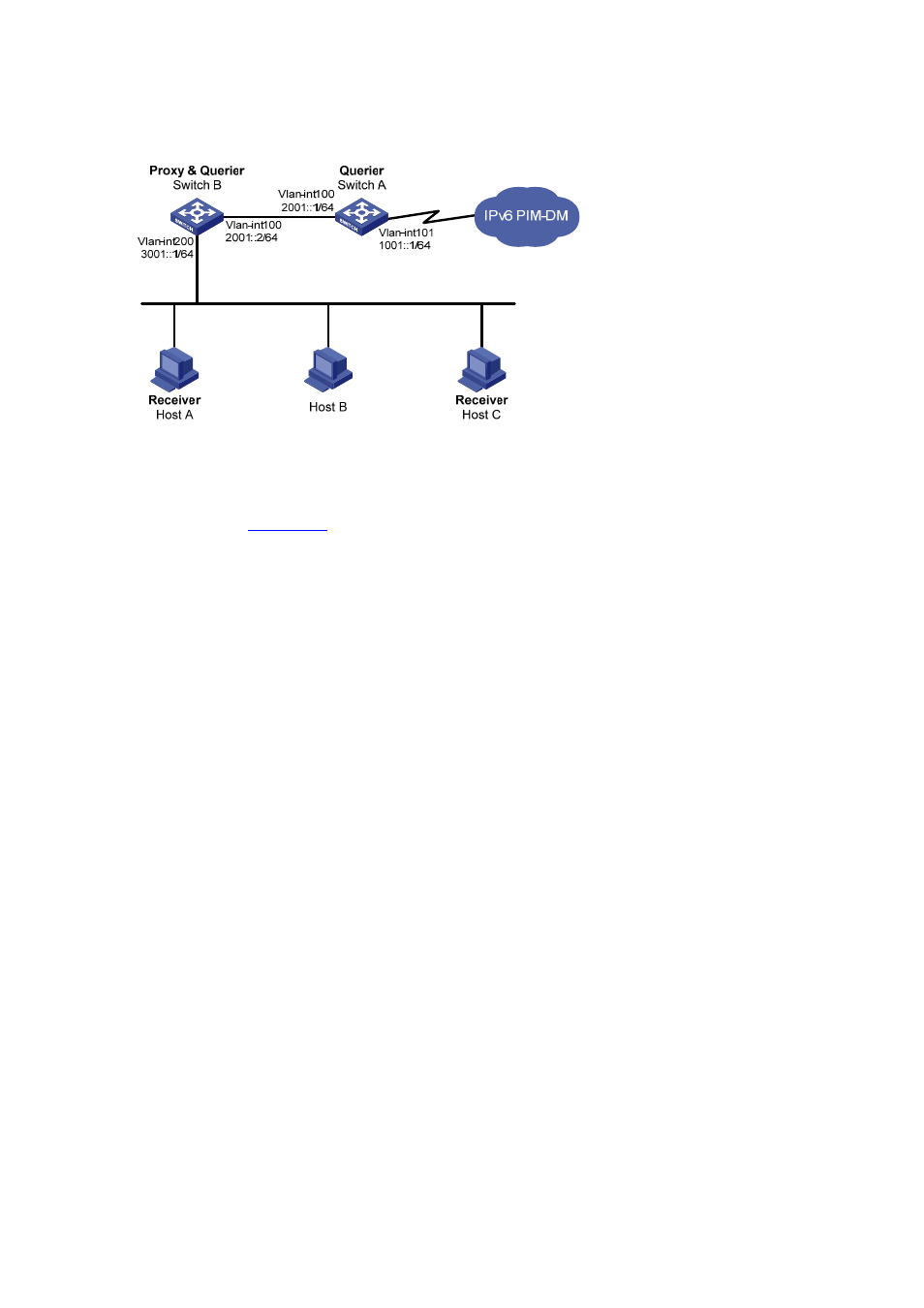
Figure 12-9 Network diagram for MLD proxying configuration
Configuration procedure
1) Enable IPv6 forwarding and configure the IPv6 addresses
Enable IPv6 forwarding on each switch and configure the IPv6 address and prefix length of each
interface as per
. The detailed configuration steps are omitted here.
2) Enable IPv6 multicast routing, IPv6 PIM-DM, MLD, and MLD proxying respectively.
# Enable IPv6 multicast routing on Switch A, IPv6 PIM-DM on VLAN-interface 101, and MLD on
VLAN-interface 100.
<SwitchA> system-view
[SwitchA] multicast ipv6 routing-enable
[SwitchA] interface vlan-interface 101
[SwitchA-Vlan-interface101] pim ipv6 dm
[SwitchA-Vlan-interface101] quit
[SwitchA] interface vlan-interface 100
[SwitchA-Vlan-interface100] mld enable
[SwitchA-Vlan-interface100] pim ipv6 dm
[SwitchA-Vlan-interface100] quit
# Enable IPv6 multicast routing on Switch B, MLD proxying on VLAN-interface 100, and MLD on
VLAN-interface 200.
<SwitchB> system-view
[SwitchB] multicast ipv6 routing-enable
[SwitchB] interface vlan-interface 100
[SwitchB-Vlan-interface100] mld proxying enable
[SwitchB-Vlan-interface100] quit
[SwitchB] interface vlan-interface 200
[SwitchB-Vlan-interface200] mld enable
[SwitchB-Vlan-interface200] quit
3) Verify the installation
Use the display mld interface command to view the MLD configuration and operation information on
an interface. For example,
# Display MLD configuration and operation information on VLAN-interface 100 of Switch B.
[SwitchB] display mld interface vlan-interface 100 verbose
Vlan-interface100(2001::2):
MLD proxy is enabled