Network diagram, Configuration procedure – H3C Technologies H3C S7500E Series Switches User Manual
Page 218
7-17
z
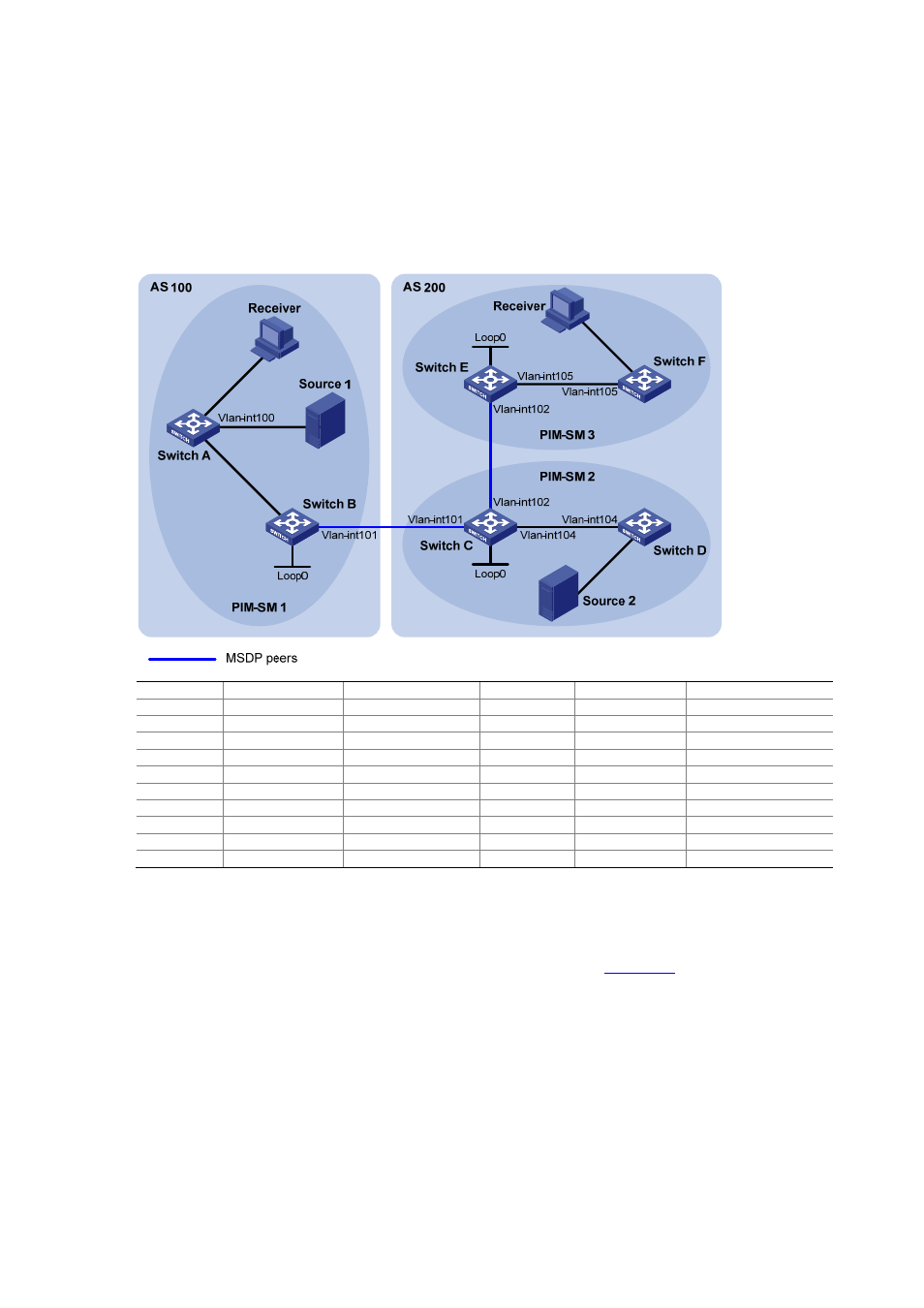
It is required that the respective Loopback 0 of Switch B, Switch C and Switch E be configured as
the C-BSR and C-RP of the respective PIM-SM domains.
z
It is required that an MSDP peering relationship be set up between Switch B and Switch C
through EBGP, and between Switch C and Switch E through IBGP.
Network diagram
Figure 7-5 Network diagram for inter-AS multicast configuration leveraging BGP routes
Vl
an
-int103
Vl
an
-int103
Vl
an-
int20
0
Vlan-
int30
0
Vl
an-
int40
0
Device Interface
IP
address
Device Interface IP
address
Switch A
Vlan-int103
10.110.1.2/24
Switch D
Vlan-int104
10.110.4.2/24
Vlan-int100
10.110.2.1/24
Vlan-int300
10.110.5.1/24
Vlan-int200
10.110.3.1/24
Switch E
Vlan-int105
10.110.6.1/24
Switch B
Vlan-int103
10.110.1.1/24
Vlan-int102
192.168.3.2/24
Vlan-int101
192.168.1.1/24
Loop0
3.3.3.3/32
Loop0 1.1.1.1/32
Switch
F
Vlan-int105 10.110.6.2/24
Switch C
Vlan-int104
10.110.4.1/24
Vlan-int400
10.110.7.1/24
Vlan-int102
192.168.3.1/24
Source 1
—
10.110.2.100/24
Vlan-int101
192.168.1.2/24
Source 2
—
10.110.5.100/24
Loop0 2.2.2.2/32
Configuration procedure
1) Configure IP addresses and unicast routing
Configure the IP address and subnet mask for each interface as per
. Detailed configuration
steps are omitted here.
Configure OSPF for interconnection between switches in each AS. Ensure the network-layer
interoperation among each AS, and ensure the dynamic update of routing information between the
switches through a unicast routing protocol. Detailed configuration steps are omitted here.
2) Enable IP multicast routing, enable PIM-SM on each interface, and configure a PIM-SM domain
border
# Enable IP multicast routing on Switch A, enable PIM-SM on each interface, and enable IGMP on the
host-side interface VLAN-interface 200.
<SwitchA> system-view