Network diagram, Configuration procedure – H3C Technologies H3C S7500E Series Switches User Manual
Page 344
12-24
z
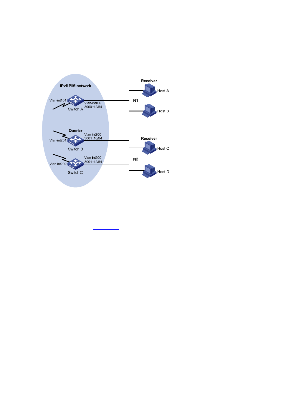
MLDv1 is required between Switch A and N1. MLDv1 is also required between the other two
switches (Switch B and Switch C) and N2. Switch B acts as the MLD querier because it has a
lower IPv6 address.
Network diagram
Figure 12-7 Network diagram for basic MLD functions configuration
Ether
net
Ethe
rnet
Configuration procedure
1) Enable IPv6 forwarding and configure IPv6 addresses and IPv6 unicast routing
Enable IPv6 forwarding on each switch and configure an IP address and prefix length for each
interface as shown in
. The detailed configuration steps are not discussed in this
document.
Configure OSPFv3 for interoperation between the switches. Ensure the network-layer interoperation
among the switches on the IPv6 PIM network and dynamic update of routing information between the
switches through a unicast routing protocol. The detailed configuration steps are omitted here.
2) Enable the IPv6 multicast routing, and enable IPv6 PIM-DM and MLD.
# Enable IPv6 multicast routing on Switch A, enable IPv6 PIM-DM on each interface, and enable MLD
on VLAN-interface 100.
<SwitchA> system-view
[SwitchA] multicast ipv6 routing-enable
[SwitchA] interface vlan-interface 100
[SwitchA-Vlan-interface100] mld enable
[SwitchA-Vlan-interface100] pim ipv6 dm
[SwitchA-Vlan-interface100] quit
[SwitchA] interface vlan-interface 101
[SwitchA-Vlan-interface101] pim ipv6 dm
[SwitchA-Vlan-interface101] quit
# Enable IPv6 multicast routing on Switch B, enable IPv6 PIM-DM on each interface, and enable MLD
on VLAN-interface 200.