Configuration procedure – H3C Technologies H3C S7500E Series Switches User Manual
Page 67
2-35
z
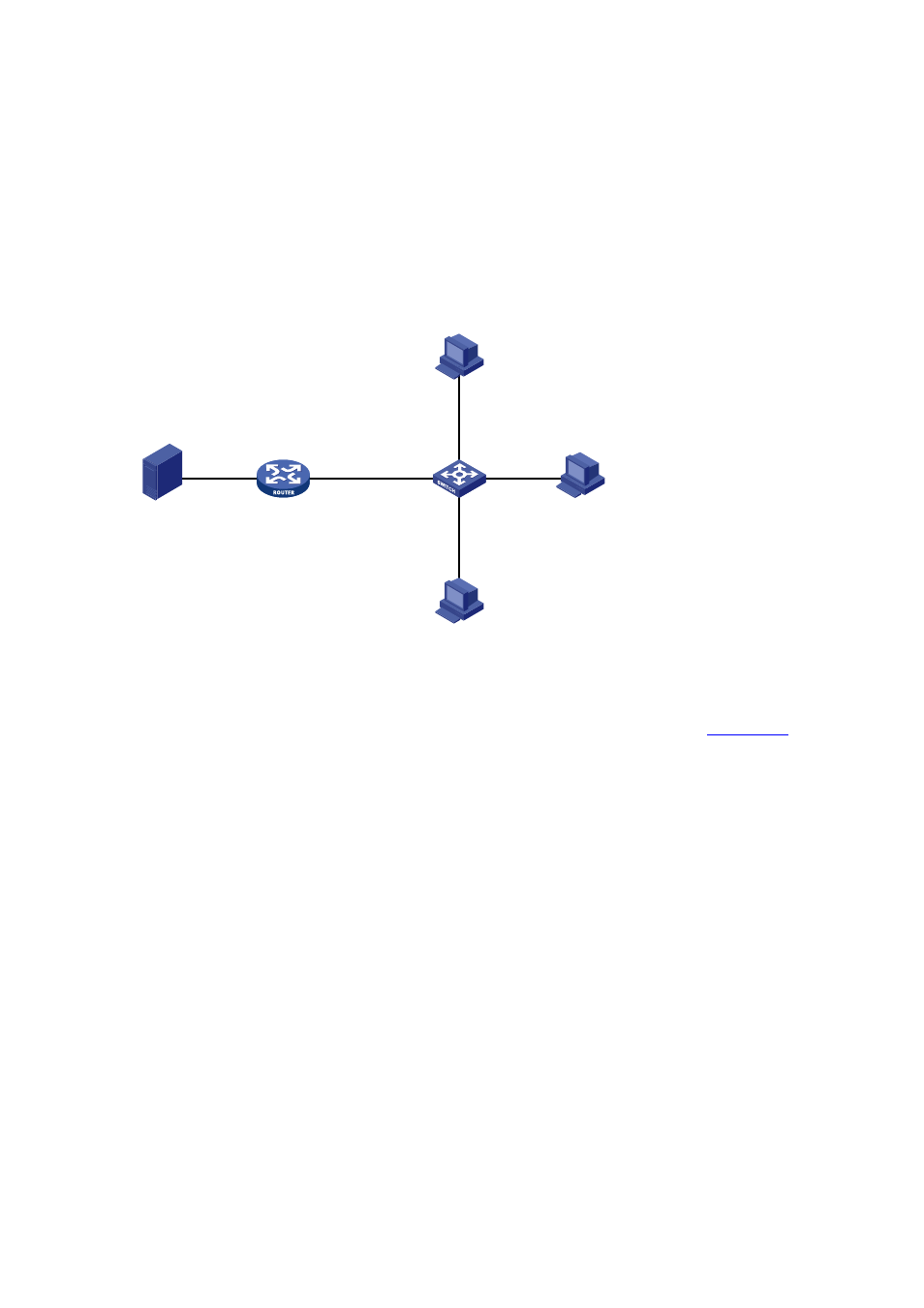
Router A connects to a multicast source through port GigabitEthernet 2/0/2, and to Switch
A through port GigabitEthernet 2/0/1.
z
Router A runs IGMPv2 and Switch A runs IGMPv2 Snooping. Router A serves as an IGMP
querier.
Configure IGMP snooping proxying on Switch A, enabling the switch to forward IGMP reports
and leave messages on behalf of attached hosts and to respond to IGMP queries from Router A
and forward the queries to the hosts on behalf of Router A.
Figure 2-7 Network diagram for IGMP snooping proxying configuration
Source
Router A
IGMP querier
Switch A
Proxy & Querier
Receiver
Host B
Host A
Host C
1.1.1.1/24
GE2/0/4
GE2/0/2
GE2/0/3
GE2/0/1
GE2/0/1
10.1.1.1/24
GE2/0/2
1.1.1.2/24
Receiver
Configuration procedure
1) Configure IP addresses for interfaces
Configure an IP address and subnet mask for each interface as per
. The
configuration steps are omitted here.
2) Configure Router A
# Enable IP multicast routing, enable PIM-DM on each interface, and enable IGMP on
GigabitEthernet 2/0/1.
<RouterA> system-view
[RouterA] multicast routing-enable
[RouterA] interface gigabitethernet 2/0/1
[RouterA-Gigabitethernet2/0/1] igmp enable
[RouterA-Gigabitethernet2/0/1] pim dm
[RouterA-Gigabitethernet2/0/1] quit
[RouterA] interface gigabitethernet 2/0/2
[RouterA-Gigabitethernet2/0/2] pim dm
[RouterA-Gigabitethernet2/0/2] quit
3) Configure Switch A
# Enable IGMP snooping globally.
<SwitchA> system-view
[SwitchA] igmp-snooping
[SwitchA-igmp-snooping] quit
# Create VLAN 100, assign ports GigabitEthernet 2/0/1 through GigabitEthernet 2/0/4 to this
VLAN, and enable IGMP snooping and IGMP snooping proxying in the VLAN.