Port-based multicast vlan configuration, Network requirements, Network diagram – H3C Technologies H3C S7500E Series Switches User Manual
Page 82: Configuration procedure
3-11
Port-Based Multicast VLAN Configuration
Network requirements
z
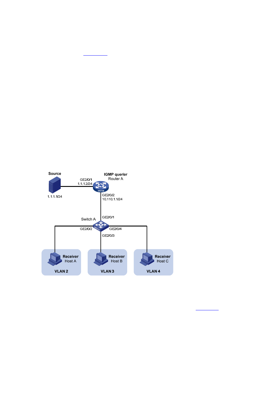
As shown in
, Router A connects to a multicast source (Source) through
GigabitEthernet 2/0/1, and to Switch A through GigabitEthernet 2/0/2.
z
IGMPv2 is required on Router A. IGMPv2 Snooping is required on Switch A. Router A acts
as the IGMP querier.
z
Switch A’s GigabitEthernet 2/0/1 belongs to VLAN 10, GigabitEthernet 2/0/2 through
GigabitEthernet 2/0/4 belong to VLAN 2 through VLAN 4 respectively, and Host A through
Host C are attached to GigabitEthernet 2/0/2 through GigabitEthernet2/0/4 of Switch A
respectively.
z
The multicast source sends multicast data to multicast group 224.1.1.1. Host A, Host B,
and Host C are receivers of the multicast group.
z
Configure the port-based multicast VLAN feature so that Router A just sends multicast data
to Switch A through the multicast VLAN and Switch A forwards the multicast data to the
receivers that belong to different user VLANs.
Network diagram
Figure 3-5 Network diagram for port-based multicast VLAN configuration
Configuration procedure
1) Configure
IP
addresses
Configure the IP address and subnet mask for each interface as per
The detailed
configuration steps are omitted here.
2) Configure Router A
# Enable IP multicast routing, enable PIM-DM on each interface, and enable IGMP on the
host-side interface GigabitEthernet 2/0/2.
<RouterA> system-view
[RouterA] multicast routing-enable
[RouterA] interface gigabitethernet 2/0/1